 |
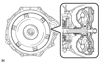
Engage the spline of the input shaft turbine runner.
AUTOMATIC TRANSMISSION ASSEMBLY > INSTALLATION |
| 1. INSTALL TRANSMISSION CONTROL CABLE BRACKET |
Install the control cable bracket with the 2 bolts.
| 2. INSPECT TORQUE CONVERTER ASSEMBLY |
| 3. INSTALL TORQUE CONVERTER ASSEMBLY |
|
Engage the spline of the input shaft turbine runner.
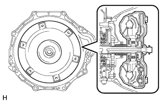 |
Engage the spline of the stator shaft and the stator while turning the torque converter assembly.
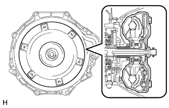 |
Turn the torque converter assembly to insert the key of the oil pump drive gear into the groove of the torque converter assembly.
Clean the torque converter set bolt holes.
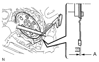 |
Using a vernier caliper and straightedge, measure dimension A between the transmission contact surface of the engine and the torque converter contact surface of the drive plate.
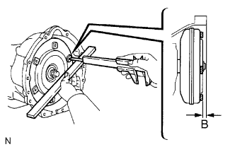 |
Using a vernier caliper and straightedge, measure dimension B shown in the illustration and check that dimension B is more than dimension A, which was measured in the previous step.
| 4. INSTALL AUTOMATIC TRANSMISSION ASSEMBLY |
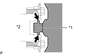 |
Apply clutch spline grease to the surface of the crankshaft that contacts the torque converter centerpiece.
| *1 | Torque Converter Centerpiece |
| *2 | Crankshaft |
While keeping the engine and automatic transmission assembly horizontal, align the knock pins with the holes in the automatic transmission assembly and Install the 5 bolts.
| 5. INSTALL DRIVE PLATE AND TORQUE CONVERTER SETTING BOLT |
Turn the crankshaft to gain access to the installation locations of the 6 drive plate torque converter setting bolts and install each bolt while holding the crankshaft pulley bolt with a wrench.
| 6. INSTALL STIFFENER PLATE |
Install the No. 2 end plate.
Install the No. 4 cylinder block insulator.
Install the stiffener plate LH to the engine and transmission with the 4 bolts.
Install the stiffener plate RH (with clamp tube) to the engine and transmission with the 4 bolts.
| 7. INSTALL WIRE HARNESS CLAMP BRACKET |
Install the wire harness clamp bracket with the bolt.
| 8. CONNECT ENGINE WIRE |
Connect the 6 connectors and attach the 3 clamps.
| 9. INSTALL REAR NO. 1 ENGINE MOUNTING INSULATOR |
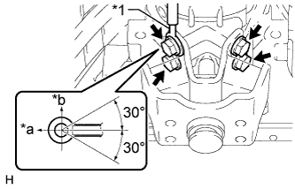 |
Install the engine mounting insulator and ground cable to the transmission with the 4 bolts.
| *1 | Ground Cable |
| *a | Front |
| *b | Upper |
| 10. INSTALL NO. 3 FRAME CROSSMEMBER SUB-ASSEMBLY |
Install the 4 set bolts of the engine mounting insulator.
Install the frame crossmember with the 4 bolts and 4 nuts.
| 11. INSTALL STARTER ASSEMBLY |
| 12. CONNECT TRANSMISSION CONTROL SHIFT CABLE ASSEMBLY |
Connect the control cable with a new clip.
Connect the control cable with the nut.
| 13. INSTALL OIL COOLER TUBE |
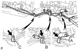 |
Loosely install the tip of the oil cooler tube inlet to the automatic transmission by hand.
Loosely install the tip of the oil cooler tube outlet to the automatic transmission by hand.
Install the 3 clamps with the 3 bolts.
Using a union nut wrench, tighten the inlet and outlet tubes.
| 14. INSTALL TRANSMISSION OIL FILLER TUBE SUB-ASSEMBLY |
Coat a new O-ring with ATF, and install it to the oil filler tube.
Install the oil filler tube with the 2 bolts.
Install the oil level dipstick.
| 15. INSTALL PROPELLER SHAFT ASSEMBLY |
| 16. INSTALL FRONT EXHAUST PIPE ASSEMBLY |
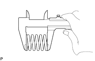 |
Using a vernier caliper, measure the free length of the compression spring.
Install the front exhaust pipe to the pipe support.
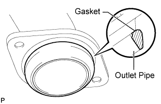 |
Install a new gasket to the outlet pipe.
Install the front exhaust pipe and 2 compression springs with the 2 bolts. Alternately tighten the bolts in several passes.
| 17. ADJUST SHIFT LEVER POSITION |
| 18. ADD AUTOMATIC TRANSMISSION FLUID |
| 19. CONNECT CABLE TO NEGATIVE BATTERY TERMINAL |
| 20. INSPECT SHIFT LEVER POSITION |
| 21. CHECK FOR EXHAUST GAS LEAKS |
| 22. CHECK AUTOMATIC TRANSMISSION FLUID |