 |
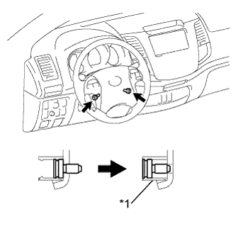
Using a T30 "TORX" socket wrench, loosen the 2 screws until the groove along the screw circumference catches on the screw case.
| *1 | Screw Case |
STEERING COLUMN ASSEMBLY > REMOVAL |
| 1. PRECAUTION |
| 2. DISCONNECT CABLE FROM NEGATIVE BATTERY TERMINAL |
| 3. PLACE FRONT WHEELS FACING STRAIGHT AHEAD |
| 4. REMOVE STEERING PAD ASSEMBLY |
|
Using a T30 "TORX" socket wrench, loosen the 2 screws until the groove along the screw circumference catches on the screw case.
| *1 | Screw Case |
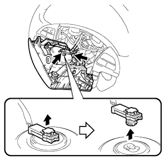 |
Pull out the steering pad from the steering wheel as shown in the illustration. Then support the steering pad with one hand.
Disconnect the horn connector.
Disconnect the connector and remove the steering pad.
| 5. REMOVE STEERING PAD SWITCH ASSEMBLY (w/ Multi-information Display) |
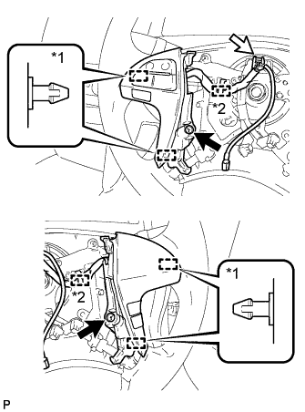 |
Disconnect the connectors and detach the 2 clamps.
| *1 | Pin |
| *2 | Clamp |
Remove the 2 screws.
Detach the 4 pins and remove the steering pad switch.
| 6. REMOVE STEERING PAD SWITCH LH (w/o Multi-information Display) |
Measure the resistance according to the value(s) in the table below.
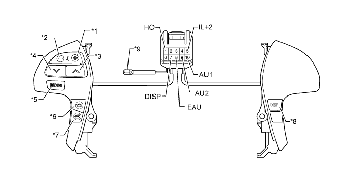
| *1 | Volume+ Switch | *2 | Volume- Switch |
| *3 | Seek+ Switch | *4 | Seek- Switch |
| *5 | MODE Switch | *6 | On Hook Switch |
| *7 | Off Hook Switch | *8 | DISP Switch |
| *9 | Horn Wire | - | - |
| Tester Connection | Switch Condition | Specified Condition |
| 9 (AU2) - 8 (EAU) | No switch pushed | 95 to 105 kΩ |
| 9 (AU2) - 8 (EAU) | MODE switch pushed | Below 2.5 Ω |
| 9 (AU2) - 8 (EAU) | On hook switch pushed | 312.6 to 345.5 Ω |
| 9 (AU2) - 8 (EAU) | Off hook switch pushed | 950 to 1050 Ω |
| 10 (AU1) - 8 (EAU) | No switch pushed | 95 to 105 kΩ |
| 10 (AU1) - 8 (EAU) | Seek+ switch pushed | Below 2.5 Ω |
| 10 (AU1) - 8 (EAU) | Seek- switch pushed | 312.6 to 345.5 Ω |
| 10 (AU1) - 8 (EAU) | Volume+ switch pushed | 950 to 1050 Ω |
| 10 (AU1) - 8 (EAU) | Volume- switch pushed | 2954.5 to 3265.5 Ω |
| 7 (DISP) - 8 (EAU) | DISP switch pushed | Below 2.5 Ω |
| 1 (HO) - Horn wire | Always | Below 2.5 Ω |
Connect the battery positive (+) lead to terminal IL+2 and the negative (-) lead to terminal EAU of the steering pad switch assembly connector.
Check that the switch illumination comes on.
| 7. REMOVE STEERING WHEEL ASSEMBLY |
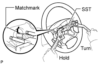 |
Remove the steering wheel set nut.
Place matchmarks on the steering wheel and main shaft.
Using SST, remove the steering wheel.
| 8. REMOVE STEERING COLUMN LOWER COVER |
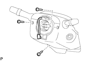 |
Remove the 3 screws and lower cover.
| 9. REMOVE STEERING COLUMN UPPER COVER |
| 10. REMOVE INSTRUMENT CLUSTER FINISH PANEL NO.1 |
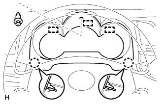 |
Remove the clip <C>.
Detach the 2 claws and 3 guides and remove the No. 1 instrument cluster finish panel.
| 11. REMOVE SPIRAL CABLE SUB-ASSEMBLY |
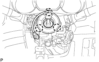 |
Disconnect the connectors from the spiral cable.
Detach the 3 claws and remove the spiral cable.
| 12. REMOVE WIPER AND WASHER SWITCH ASSEMBLY |
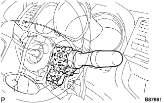 |
Disconnect the connectors.
Detach the claw and remove the windshield wiper switch.
| 13. REMOVE HEADLIGHT DIMMER SWITCH ASSEMBLY |
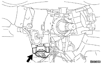 |
Disconnect the connector.
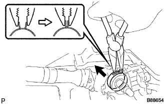 |
Using needle-nose pliers, remove the band clamp as shown in the illustration.
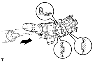 |
While loosening the band clamp as shown in the illustration, detach the claw to remove the headlight dimmer switch assembly.
| 14. REMOVE UPPER INSTRUMENT PANEL SUB-ASSEMBLY |
| 15. REMOVE LOWER INSTRUMENT PANEL SUB-ASSEMBLY |
Using a clip remover, remove the 2 clips <B>.
Remove the 2 bolts <C>, nut <D> and 3 screws <E>.
Disconnect the hood lock control cable, fuel lid lock control cable and DLC3.
Disconnect the connectors and detach the clamps.
Detach the 2 guides and remove the lower instrument panel.
for Automatic Air Conditioning System:
Disconnect the room temperature sensor.
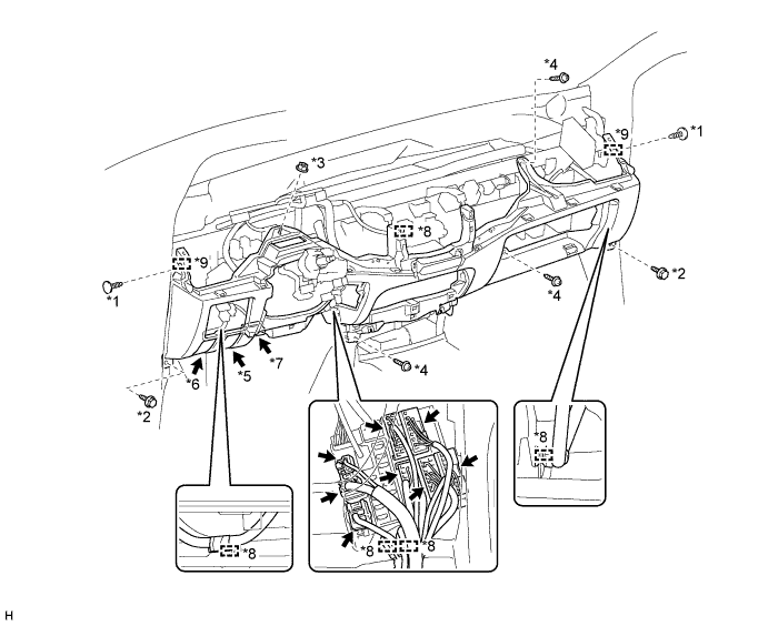
| *1 | Clip <B> | *2 | Bolt <C> |
| *3 | Nut <D> | *4 | Screw <E> |
| *5 | Hood Lock Control Cable | *6 | Fuel Lid Lock Control Cable |
| *7 | DLC3 | *8 | Clamp |
| *9 | Guide | - | - |
| 16. DISCONNECT STEERING SLIDING YOKE |
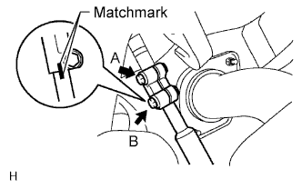 |
Loosen the bolt labeled A.
Place matchmarks on the steering yoke and steering intermediate shaft.
Remove the bolt labeled B.
| 17. DISCONNECT CONNECTOR |
Disconnect the connectors and wire harness clamps from the steering column.
| 18. REMOVE STEERING COLUMN HOLE COVER SUB-ASSEMBLY |
Remove the 3 bolts and cover.
| 19. REMOVE STEERING COLUMN ASSEMBLY |
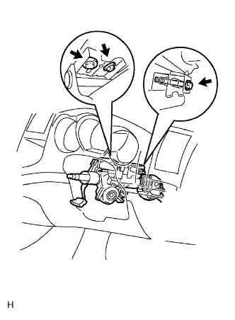 |
Remove the 3 bolts and pull out the steering column together with the steering sliding w/ coupling yoke.