Home › ENGINE ยท 2TR-FE › EMISSION CONTROL › EMISSION CONTROL SYSTEM (w/o Secondary Air Injection System)

EMISSION CONTROL SYSTEM (w/o Secondary Air Injection System) > ON-VEHICLE INSPECTION

for Preparation Click here


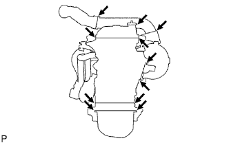
1. CHECK FOR LEAKS


    A099255E01
  1. Visually check that the hoses, connections and gaskets have no cracks, leaks or damage.

    NOTICE:
    1. Detachment or other problems with the engine oil dipstick, filler cap, PCV hose and other components may cause the engine to run improperly.
    1. Air suction caused by disconnections, looseness or cracks in the parts of the air induction system between the throttle body and cylinder head will cause engine failure or engine malfunctions.
    If the result is not as specified, replace parts as necessary.


2. CHECK PURGE VSV


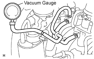
    A099569E01
  1. Check that the vacuum hose is connected correctly.

  1. Disconnect the vacuum hose from the canister, and connect a vacuum gauge.

  1. Using the flowchart below, perform a purge VSV operation inspection when the engine coolant temperature is 55°C (131°F) or less (while the engine is cold (purge VSV is closed)).

    HINT:
    The ECM turns the purge VSV off so that the route between the canister and intake manifold is closed, and fuel vapor in the canister is not purged to the intake manifold.


    1. Purge VSV operation flowchart.
      1. When the engine is idling or running and at 2,500 rpm, the vacuum gauge indicates 1 kPa (25 mmHg, 0.3 in.Hg) or less.

      Result:
      Result
      Procedure
      Yes
      Purge VSV operation normal
      No
      Go to next step

      2. Inspect the purge VSV (Click here).

      Result:
      Result
      Procedure
      OK
      Check wire harness and ECM
      NG
      Replace purge VSV

  1. Using the flowchart below, perform a purge VSV operation inspection when the engine coolant temperature is 80°C (146°F) or more (while the engine is hot (purge VSV is opened)).

    HINT:
    The ECM turns the purge VSV on so that a vacuum is created in the intake manifold and the canister's fuel vapors are purged to the intake manifold.


    1. Purge VSV operation flowchart.
      1. When the engine is idling, the vacuum gauge indicates 40 kPa (300 mmHg, 11.8 in.Hg) or more.

      Result:
      Result
      Procedure
      Yes
      Purge VSV operation normal
      No
      Go to next step

      2. Inspect the purge VSV (Click here).

      Result:
      Result
      Procedure
      OK
      Check wire harness and ECM
      NG
      Replace purge VSV