 |
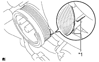
Align the matchmarks of the crankshaft pulley and timing gear case cover by rotating the crankshaft clockwise.
| *1 | Matchmark |
- HINT:
- Make sure that both cam lobes (intake side and exhaust side) of the No. 1 cylinder face upward.
VALVE CLEARANCE > ADJUSTMENT |
| 1. REMOVE CYLINDER HEAD COVER SUB-ASSEMBLY |
| 2. SET NO. 1 CYLINDER TO TDC/COMPRESSION |
|
Align the matchmarks of the crankshaft pulley and timing gear case cover by rotating the crankshaft clockwise.
| *1 | Matchmark |
| 3. INSPECT VALVE CLEARANCE |
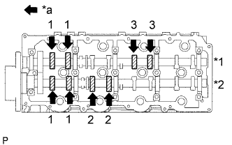 |
Check only the valves indicated.
Using a feeler gauge, measure the clearance between the valve lifter and camshaft.
| Item | Specified Condition |
| Intake | 0.2 to 0.3 mm (0.008 to 0.012 in.) |
| Exhaust | 0.35 to 0.45 mm (0.014 to 0.018 in.) |
| *1 | Exhaust |
| *2 | Intake |
| *a | Front |
Turn the crankshaft 360° to set the No. 4 cylinder to TDC/compression.
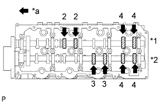 |
Check only the valves indicated.
Using a feeler gauge, measure the clearance between the valve lifter and camshaft.
| Item | Specified Condition |
| Intake | 0.2 to 0.3 mm (0.008 to 0.012 in.) |
| Exhaust | 0.35 to 0.45 mm (0.014 to 0.018 in.) |
| *1 | Exhaust |
| *2 | Intake |
| *a | Front |
| 4. ADJUST VALVE CLEARANCE |
Remove the injector.
Remove the timing belt.
Remove the camshaft timing pulley.
Remove the No. 2 timing belt cover.
Remove the camshafts.
Remove the valve lifters.
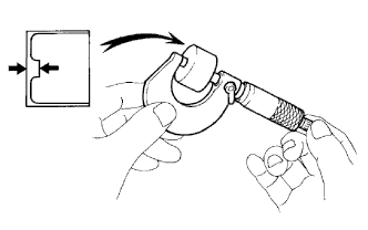 |
Using a micrometer, measure the thickness of the removed lifter.
Calculate the thickness of a new lifter so that the valve clearance is within the specified range.
| A | B | C |
| New lifter thickness | Used lifter thickness | Measured valve clearance |
Select a new lifter with a thickness as close as possible to the calculated values.
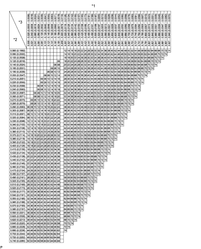
| *1 | Valve Lifter Selection Chart (Intake) | *2 | Installed lifter thickness mm (in.) |
| *3 | Measured clearance mm (in.) | - | - |
| Lifter No. | Specified Condition | Lifter No. | Specified Condition | Lifter No. | Specified Condition |
| 06 | 5.06 mm (0.1992 in.) | 30 | 5.30 mm (0.2087 in.) | 54 | 5.54 mm (0.2181 in.) |
| 08 | 5.08 mm (0.2000 in.) | 32 | 5.32 mm (0.2094 in.) | 56 | 5.56 mm (0.2189 in.) |
| 10 | 5.10 mm (0.2008 in.) | 34 | 5.34 mm (0.2102 in.) | 58 | 5.58 mm (0.2197 in.) |
| 12 | 5.12 mm (0.2016 in.) | 36 | 5.36 mm (0.2110 in.) | 60 | 5.60 mm (0.2205 in.) |
| 14 | 5.14 mm (0.2024 in.) | 38 | 5.38 mm (0.2118 in.) | 62 | 5.62 mm (0.2213 in.) |
| 16 | 5.16 mm (0.2031 in.) | 40 | 5.40 mm (0.2126 in.) | 64 | 5.64 mm (0.2220 in.) |
| 18 | 5.18 mm (0.2039 in.) | 42 | 5.42 mm (0.2134 in.) | 66 | 5.66 mm (0.2228 in.) |
| 20 | 5.20 mm (0.2047 in.) | 44 | 5.44 mm (0.2142 in.) | 68 | 5.68 mm (0.2236 in.) |
| 22 | 5.22 mm (0.2055 in.) | 46 | 5.46 mm (0.2150 in.) | 70 | 5.70 mm (0.2244 in.) |
| 24 | 5.24 mm (0.2063 in.) | 48 | 5.48 mm (0.2157 in.) | 72 | 5.72 mm (0.2252 in.) |
| 26 | 5.26 mm (0.2071 in.) | 50 | 5.50 mm (0.2165 in.) | 74 | 5.74 mm (0.2260 in.) |
| 28 | 5.28 mm (0.2079 in.) | 52 | 5.52 mm (0.2173 in.) | - | - |
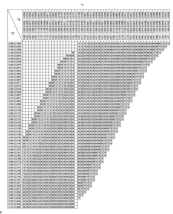
| *1 | Valve Lifter Selection Chart (Exhaust) | *2 | Installed lifter thickness mm (in.) |
| *3 | Measured clearance mm (in.) | - | - |
| Lifter No. | Specified Condition | Lifter No. | Specified Condition | Lifter No. | Specified Condition |
| 06 | 5.06 mm (0.1992 in.) | 30 | 5.30 mm (0.2087 in.) | 54 | 5.54 mm (0.2181 in.) |
| 08 | 5.08 mm (0.2000 in.) | 32 | 5.32 mm (0.2094 in.) | 56 | 5.56 mm (0.2189 in.) |
| 10 | 5.10 mm (0.2008 in.) | 34 | 5.34 mm (0.2102 in.) | 58 | 5.58 mm (0.2197 in.) |
| 12 | 5.12 mm (0.2016 in.) | 36 | 5.36 mm (0.2110 in.) | 60 | 5.60 mm (0.2205 in.) |
| 14 | 5.14 mm (0.2024 in.) | 38 | 5.38 mm (0.2118 in.) | 62 | 5.62 mm (0.2213 in.) |
| 16 | 5.16 mm (0.2031 in.) | 40 | 5.40 mm (0.2126 in.) | 64 | 5.64 mm (0.2220 in.) |
| 18 | 5.18 mm (0.2039 in.) | 42 | 5.42 mm (0.2134 in.) | 66 | 5.66 mm (0.2228 in.) |
| 20 | 5.20 mm (0.2047 in.) | 44 | 5.44 mm (0.2142 in.) | 68 | 5.68 mm (0.2236 in.) |
| 22 | 5.22 mm (0.2055 in.) | 46 | 5.46 mm (0.2150 in.) | 70 | 5.70 mm (0.2244 in.) |
| 24 | 5.24 mm (0.2063 in.) | 48 | 5.48 mm (0.2157 in.) | 72 | 5.72 mm (0.2252 in.) |
| 26 | 5.26 mm (0.2071 in.) | 50 | 5.50 mm (0.2165 in.) | 74 | 5.74 mm (0.2260 in.) |
| 28 | 5.28 mm (0.2079 in.) | 52 | 5.52 mm (0.2173 in.) | - | - |
Install the selected valve lifters.
Install the camshafts.
Install the No. 2 timing belt cover.
Install the camshaft timing pulley.
Install the timing belt.
Install the fuel injector.
| 5. INSTALL CYLINDER HEAD COVER SUB-ASSEMBLY |
| 6. INSPECT FOR COOLANT LEAK |
Check for engine coolant leaks (Click here).
| 7. BLEED AIR FROM FUEL SYSTEM |
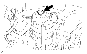 |
Using the hand pump mounted on the fuel filter cap, bleed the air from the fuel system. Continue pumping until the pump resistance increases.
Start the engine.
When the engine can be started, proceed to the next step.
If the engine cannot be started, bleed the air again using the hand pump until the hand pump resistance increases (refer to the procedures above). Then start the engine.
Turn the ignition switch off.
Connect the intelligent tester to the DLC3.
Turn the ignition switch to ON and turn the intelligent tester on.
Clear the DTCs.
Start the engine.*1
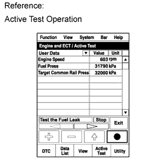 |
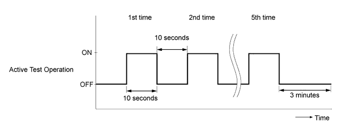
Enter the following menus: Powertrain / Engine and ECT / Active Test / Test the Fuel Leak.*2
Perform the following test 5 times with on/off intervals of 10 seconds: Active Test / Test the Fuel Leak.*3
Allow the engine to idle for 3 minutes or more after performing the Active Test for the fifth time.
Enter the following menus: Powertrain / Engine and ECT / DTC.
Read Current DTCs.
Clear the DTCs.
Repeat steps *1 to *3.
Enter the following menus: Powertrain / Engine and ECT / DTC.
Read Current DTCs.
| 8. INSPECT FOR FUEL LEAK |
Check that there are no leaks from any part of the fuel system when the engine is stopped. If there is fuel leakage, repair or replace parts as necessary.
Start the engine and check that there are no leaks from any part of the fuel system. If there is fuel leakage, repair or replace parts as necessary.
Disconnect the return hose from the common rail.
Start the engine and check for fuel leaks from the return pipe.
If there is fuel leakage, replace the common rail.
Connect the intelligent tester to the DLC3.
Start the engine and push the intelligent tester main switch on.
Select the Fuel Leak test from the Active Test mode on the intelligent tester.
If the intelligent tester is not available, fully depress the accelerator pedal quickly. Increase the engine speed to the maximum and maintain that speed for 2 seconds. Repeat this operation several times.
Check that there are no leaks from any part of the fuel system.
Reconnect the return hose to the common rail.
| 9. INSPECT FOR OIL LEAK |