 |
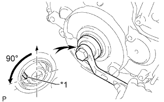
Using the crankshaft pulley bolt, set the No. 1 cylinder to 90° BTDC/compression.
| *1 | Key |
- HINT:
- Set the No. 1 cylinder to 90° BTDC/compression to prevent the top of the piston from hitting against the valve head.
CAMSHAFT > INSTALLATION |
| 1. INSTALL CAMSHAFT |
|
Using the crankshaft pulley bolt, set the No. 1 cylinder to 90° BTDC/compression.
| *1 | Key |
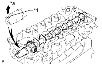 |
Install the camshaft.
Apply engine oil to the thrust portion of the camshaft.
Place the camshaft on the cylinder head with the key groove facing upward.
| *1 | Key Groove |
| *a | Upward |
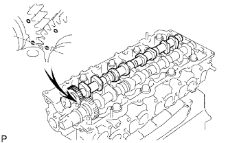 |
Align the timing marks (1-dot marks) of the camshaft drive and driven main gears and set the No. 2 camshaft in place.
Remove any old seal packing (FIPG material) from the camshaft bearing cap.
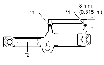 |
Apply seal packing to the specified areas shown in the illustration.
| *1 | Seal Packing |
| *2 | Oil Passage |
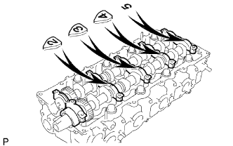 |
Install the 5 bearing caps to their proper locations.
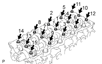 |
Apply a light coat of engine oil to the threads and under the heads of the bearing cap bolts.
Install and uniformly tighten the 15 bearing cap bolts in several passes in the sequence shown in the illustration.
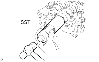 |
Install a new camshaft oil seal.
Apply MP grease to the lip of a new oil seal.
Using SST and a hammer, tap in the oil seal until its surface is flush with the surfaces of the camshaft bearing cap and cylinder head.
| 2. INSTALL NO. 2 TIMING BELT COVER |
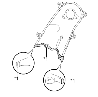 |
Apply seal packing (FIPG) to the specified areas shown in the illustration.
| *1 | Seal Packing |
Clean the bolts and their holes.
Apply adhesive to 2 or 3 threads at the end of 4 bolts.
Install the No. 2 timing belt cover with the 4 bolts and nut.
| 3. INSTALL CAMSHAFT TIMING PULLEY |
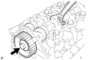 |
Install the camshaft timing pulley.
Fasten the bolt of the camshaft timing pulley by holding the camshaft with a wrench.
| 4. INSTALL NO. 1 TIMING BELT IDLER SUB-ASSEMBLY |
Using a 10 mm hexagon wrench, install a new washer and the No. 1 timing belt idler with the bolt.
Check that the idler pulley moves smoothly.
If the idler pulley does not move smoothly, check the installation condition of the idler and washer.
| 5. INSTALL TIMING BELT |
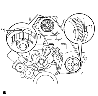 |
Check that the timing marks are aligned as shown in the illustration.
| *1 | Timing Mark |
Install the timing belt to the pump drive shaft pulley, camshaft timing pulley and No. 1 timing belt idler in sequence.
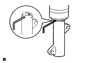 |
Place the tensioner upright. Then set a press on the top of the tensioner.
Using the press, slowly push in the push rod using 981 to 9800 N (100 to 999 kgf, 220 to 2203 lbf) of force.
Align the holes of the push rod and housing. Then pass a 1.5 mm hexagon wrench through the holes to fix the push rod in place.
Temporarily install the timing belt tensioner with the 2 bolts while pushing the idler pulley toward the timing belt.
Tighten the 2 bolts.
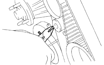 |
Remove the 1.5 mm hexagon wrench from the tensioner.
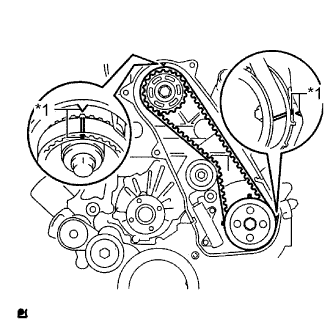 |
Turn the crankshaft clockwise 720° and check that the timing marks are aligned as shown in the illustration.
| *1 | Timing Mark |
| 6. INSPECT AND ADJUST VALVE CLEARANCE |
| 7. INSTALL NO. 1 TIMING BELT COVER |
Install the timing belt cover and 6 washers with the 6 bolts.
| 8. INSTALL INJECTOR ASSEMBLY |
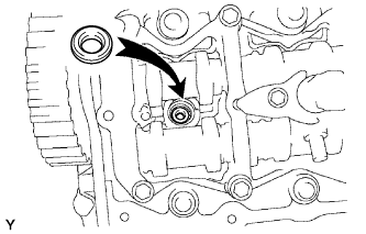 |
Install 4 new injection nozzle seats to the cylinder head.
Apply a small amount of clean engine oil to 4 new O-rings.
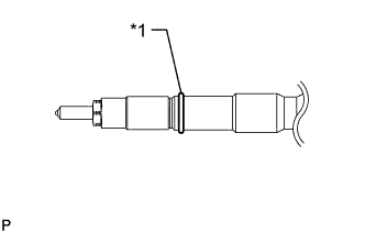 |
Install an O-ring to each injector as shown in the illustration.
| *1 | New O-Ring |
Insert the 4 injectors into the cylinder head.
For an injector that has been replaced with a new injector, register the injector compensation code .
Temporarily install the 4 injection pipes with the union nuts.
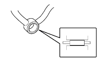 |
Check the nozzle leakage pipe. Check that there are no scratches or dents on the 5 union seal surfaces.
If scratches or dents are present, replace the nozzle leakage pipe.
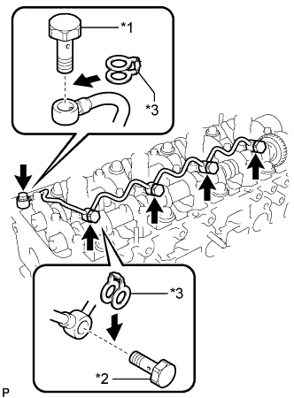 |
Set the nozzle leakage pipe and 5 new gaskets in place.
| *1 | Union Bolt |
| *2 | Injector Hollow Screw |
| *3 | New Gasket |
Apply a small amount of oil to the 4 injector hollow screws and union bolt.
Temporarily install the nozzle leakage pipe with the 4 injector hollow screws and union bolt.
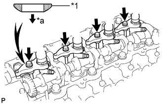 |
Temporarily install 4 new washers and the 4 No. 1 nozzle holder clamps with the 4 bolts.
| *1 | Washer |
| *a | Downward |
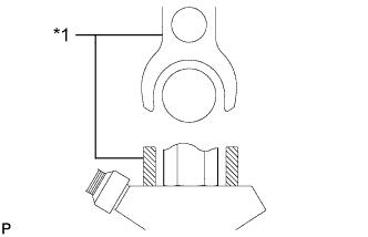 |
| *1 | No. 1 Nozzle Holder Clamp |
Tighten the 4 holder clamp bolts.
Remove the 4 injection pipes.
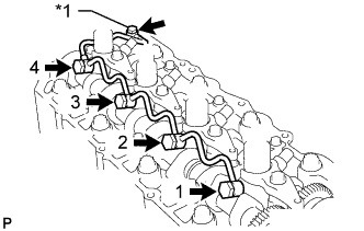 |
Tighten the 4 injector hollow screws in order from 1 to 4.
| *1 | Union Bolt |
Tighten the union bolt.
| 9. INSPECT FOR FUEL LEAK |
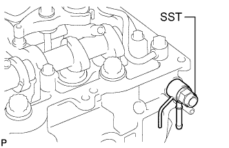 |
Check that there are no leaks from the nozzle leakage pipe connection.
Install the gasket and No. 2 nozzle leakage pipe to the cylinder head with SST (check valve).
Apply a small amount of soapy water (or other fluid for detecting fuel leakage) on the nozzle leakage pipe connection.
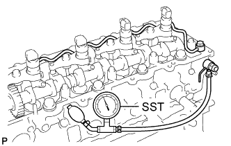 |
Install SST (turbocharger pressure gauge) to the fuel return side of the nozzle leakage pipe and maintain 100 kPa (1.0 kgf/cm2, 15 psi) of pressure for 60 seconds to check that no bubbles form.
After checking for fuel leaks, wipe off the soapy water from the nozzle leakage pipe connection.
Remove SST, the No. 2 nozzle leakage pipe and gasket.
| 10. INSTALL CYLINDER HEAD COVER SUB-ASSEMBLY |
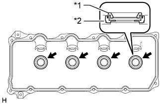 |
Install 4 new No. 3 cylinder head cover gaskets to the cylinder head cover in the directions shown in the illustration.
| *1 | No. 3 Cylinder Head Cover Gasket |
| *2 | Cylinder Head Cover |
Remove any old seal packing (FIPG material) from the cylinder head.
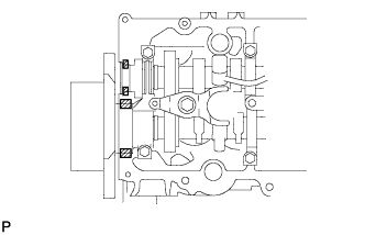 |
Apply seal packing to the specific areas shown in the illustration.
 | Seal Packing |
Install a new cylinder head cover gasket and the cylinder head cover with the 10 bolts and 2 nuts.
Install 4 new nozzle holder seals.
Connect the ventilation hose.
Connect the 4 injector connectors and install the 3 bolts.
| 11. INSTALL NO. 2 NOZZLE LEAKAGE PIPE ASSEMBLY |
Temporarily install the No. 2 nozzle leakage pipe with the 2 bolts.
Temporarily install a new gasket and the union bolt.
Tighten the 2 bolts and union bolt.
Connect the 3 fuel hoses.
| 12. INSTALL NO. 4 INJECTION PIPE SUB-ASSEMBLY |
Temporarily install the No. 4 injection pipe with the union nuts.
Install the 2 bolts.
Using a 17 mm union nut wrench, tighten the injection pipe union nuts on the common rail side.
Using a 17 mm union nut wrench, tighten the injection pipe union nuts on the injector side.
| 13. INSTALL NO. 1, NO. 2 AND NO. 3 INJECTION PIPE SUB-ASSEMBLY |
Temporarily install the No. 1, No. 2 and No. 3 injection pipes with the union nuts.
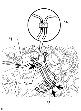 |
Install the No. 2 and No. 3 injection pipe clamps with the bolt and 2 nuts as shown in the illustration.
| *1 | No. 1 Injection Pipe |
| *2 | No. 2 Injection Pipe Clamp |
| *3 | No. 3 Injection Pipe Clamp |
| *4 | Painted Mark |
Using a 17 mm union nut wrench, tighten the injection pipe union nuts on the common rail side.
Using a 17 mm union nut wrench, tighten the injection pipe union nuts on the injector side.
| 14. INSTALL ENGINE COVER BRACKET |
Install the engine cover bracket with the 2 bolts.
| 15. INSTALL NO. 2 AIR CLEANER PIPE SUB-ASSEMBLY |
Connect the pipe (with the 2 air hoses) and install the bolt.
Tighten the 2 clamps.
Connect the vacuum hose to the gas filter.
Connect the manifold absolute pressure sensor connector.
| 16. INSTALL NO. 1 ENGINE COVER SUB-ASSEMBLY |
Attach the 4 claws to the pins of the cover bracket to install the engine cover.
| 17. INSTALL FAN SHROUD |
Install the fan pulley to the engine water pump.
Install the fan shroud together with the fluid coupling with fan between the radiator and engine component.
Install the fluid coupling with fan to the fan pulley with the 4 nuts.
Tighten the nuts as much as possible by hand.
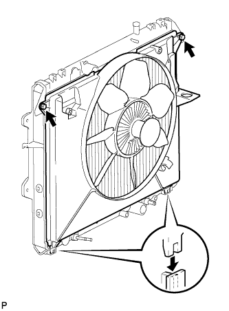 |
Attach the claws of the fan shroud to the radiator.
Install the fan shroud with the 2 bolts.
Install the fan and generator V belt (Click here).
Tighten the 4 nuts of the fluid coupling with fan.
Install the radiator reservoir with the 2 bolts.
Connect the No. 1 and No. 2 water by-pass hoses to the radiator.
Install the oil reservoir with the 3 bolts.
| 18. INSTALL RADIATOR HOSE INLET |
Connect the radiator hose inlet to the radiator.
| 19. ADD ENGINE OIL |
Add new engine oil.
| Oil Grade | Oil Viscosity (SAE) |
| G-DLD1, API CF-4 or CF (You may also use API CE or CD) | - 5W-30 - 10W-30 - 15W-40 - 20W-50 |
| Item | Specified Condition |
| Drain and refill without oil filter change | 6.6 liters (7.0 US qts, 5.8 Imp. qts) |
| Drain and refill with oil filter change | 6.9 liters (7.3 US qts, 6.1 Imp. qts) |
| Dry fill | 7.4 liters (7.8 US qts, 6.5 Imp. qts) |
Install the oil filler cap.
| 20. BLEED AIR FROM FUEL SYSTEM |
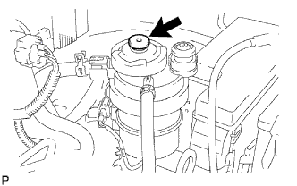 |
Using the hand pump mounted on the fuel filter cap, bleed the air from the fuel system. Continue pumping until the pump resistance increases.
Check if the engine starts.
When the engine can be started, proceed to the next step.
If the engine cannot be started, bleed the air again using the hand pump until the hand pump resistance increases (refer to the procedures above). Then start the engine.
Turn the ignition switch off.
Connect the intelligent tester to the DLC3.
Turn the ignition switch to ON and turn the intelligent tester on.
Clear the DTCs (Click here).
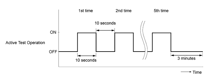
Start the engine.*1
Enter the following menus: Powertrain / Engine / Active Test / Test the Fuel Leak.*2
Perform the following test 5 times with on/off intervals of 10 seconds: Active Test / Test the Fuel Leak.*3
Allow the engine to idle for 3 minutes or more after performing the Active Test for the fifth time.
Enter the following menus: Powertrain / Engine / DTC.
Read Current DTCs.
Clear the DTCs (Click here).
Repeat steps *1 to *3.
Enter the following menus: Powertrain / Engine / DTC.
Read Current DTCs.
| 21. ADD ENGINE COOLANT |
Tighten the radiator drain cock plug by hand.
Tighten the cylinder block drain cock plug.
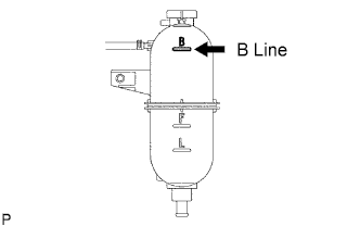 |
Fill the radiator with TOYOTA Super Long Life Coolant (SLLC) to the reservoir tank's B line.
| Item | Specified Condition |
| A/T | 11.1 liters (11.7 US qts, 9.8 Imp. qts) |
| M/T | 9.8 liters (10.4 US qts, 8.6 Imp. qts) |
Press the inlet and outlet radiator hoses several times by hand, and then check the level of the coolant.
If the coolant level drops below the B line, add TOYOTA SLLC to the B line.
Install the radiator reservoir cap.
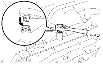 |
Using a wrench, install the vent plug.
Bleed air from the cooling system.
Warm up the engine until the thermostat opens. While the thermostat is open, circulate the coolant for several minutes.
Maintain the engine speed at 2,500 to 3,000 rpm.
Press the inlet and outlet radiator hoses several times by hand to bleed air.
Stop the engine and wait until the coolant cools down to ambient temperature.
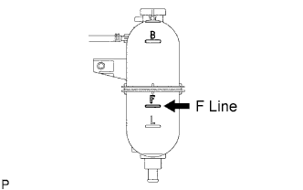 |
After the coolant cools down, check that the coolant level is at the F line.
If the coolant level is below the F line, add TOYOTA SLLC to the F line.
| 22. INSPECT FOR COOLANT LEAK |
Fill the radiator with coolant and attach a radiator cap tester.
Warm up the engine.
Using the radiator cap tester, increase the pressure inside the radiator to 118 kPa (1.2 kgf/cm2, 17 psi), and check that the pressure does not drop.
If the pressure drops, check the hoses, radiator and water pump for leaks. If no external leaks are found, check the heater core, cylinder block and head.
| 23. INSPECT FOR OIL LEAK |
Start the engine. Make sure that there are no oil leaks from the areas that were worked on.
| 24. INSPECT FOR FUEL LEAK |
Check that there are no leaks from any part of the fuel system when the engine is stopped. If there is fuel leakage, repair or replace parts as necessary.
Start the engine and check that there are no leaks from any part of the fuel system. If there is fuel leakage, repair or replace parts as necessary.
Disconnect the return hose from the common rail.
Start the engine and check for fuel leaks from the return pipe.
If there is fuel leakage, replace the common rail.
Connect the intelligent tester to the DLC3.
Start the engine and turn the intelligent tester main switch on.
Select the Fuel Leak test from the Active Test mode on the intelligent tester.
If the intelligent tester is not available, fully depress the accelerator pedal quickly. Increase the engine speed to the maximum and maintain that speed for 2 seconds. Repeat this operation several times.
Check that there are no leaks from any part of the fuel system.
Reconnect the return hose to the common rail.
| 25. INSTALL NO. 1 ENGINE UNDER COVER |
| 26. INSPECT ENGINE OIL LEVEL |
Warm up the engine, stop the engine and wait 5 minutes. The engine oil level should be between the dipstick low level mark and full level mark.
If low, check for leakage and add oil up to the full level mark.