 |
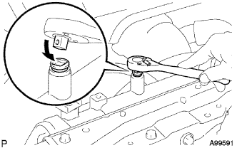
Drain the coolant by removing the radiator reservoir cap and, using a wrench, remove the vent plug.
CAMSHAFT > REMOVAL |
| 1. REMOVE NO. 1 ENGINE UNDER COVER |
| 2. DRAIN ENGINE COOLANT |
Loosen the radiator drain cock plug.
|
Drain the coolant by removing the radiator reservoir cap and, using a wrench, remove the vent plug.
Loosen the cylinder block drain cock plug.
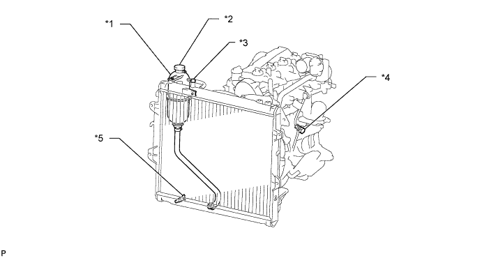
| *1 | Radiator Reservoir | *2 | Radiator Reservoir Cap |
| *3 | Vent Plug | *4 | Cylinder Block Drain Cock Plug |
| *5 | Radiator Drain Cock Plug | - | - |
| 3. DRAIN ENGINE OIL |
Remove the oil filler cap.
Remove the oil pan drain plug and gasket, and then drain the engine oil into a container.
Wipe the oil pan and drain plug.
Install a new gasket and the oil pan drain plug.
| 4. REMOVE RADIATOR HOSE INLET |
| 5. REMOVE FAN SHROUD |
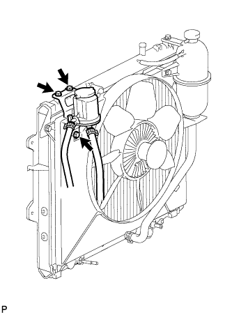 |
Remove the 3 bolts and oil reservoir.
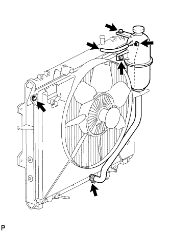 |
Disconnect the No. 1 and No. 2 water by-pass hoses from the radiator.
Remove the 2 bolts and radiator reservoir.
Loosen the 4 nuts holding the fluid coupling with fan.
Remove the fan and generator V belt (Click here).
Remove the 2 bolts holding the fan shroud.
Remove the 4 nuts of the fluid coupling with fan, and then remove the fan shroud together with the fluid coupling with fan.
Remove the fan pulley from the engine water pump.
| 6. REMOVE NO. 2 AIR CLEANER PIPE SUB-ASSEMBLY |
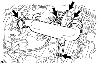 |
Disconnect the manifold absolute pressure sensor connector.
Disconnect the vacuum hose from the gas filter.
Loosen the 2 clamps.
Remove the bolt and disconnect the No. 2 air cleaner pipe together with the 2 air hoses.
| 7. REMOVE NO. 1, NO. 2 AND NO. 3 INJECTION PIPE SUB-ASSEMBLY |
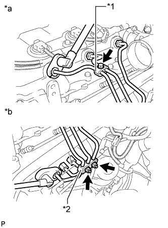 |
Remove the bolt and No. 2 injection pipe clamp.
| *1 | No. 2 Injection Pipe Clamp |
| *2 | No. 3 Injection Pipe Clamp |
| *a | Injector Side |
| *b | Common Rail Side |
Remove the 2 nuts and No. 3 injection pipe clamp.
Using a 17 mm union nut wrench, loosen the union nuts and remove the No. 1, No. 2 and No. 3 injection pipes.
| 8. REMOVE NO. 4 INJECTION PIPE SUB-ASSEMBLY |
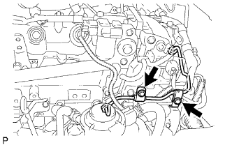 |
Remove the 2 bolts and disconnect the 2 injection pipe clamps.
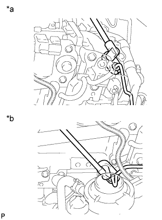 |
Using a 17 mm union nut wrench, loosen the union nuts and remove the No. 4 injection pipe.
| *a | Injector Side |
| *b | Common Rail Side |
| 9. REMOVE NO. 2 NOZZLE LEAKAGE PIPE ASSEMBLY |
Disconnect the 3 fuel hoses.
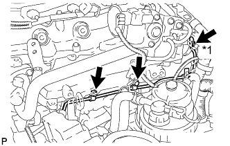 |
Remove the union bolt, 2 bolts, No. 2 nozzle leakage pipe and gasket.
| *1 | Union Bolt |
| 10. REMOVE CYLINDER HEAD COVER SUB-ASSEMBLY |
Remove the 3 bolts and disconnect the 4 injector connectors.
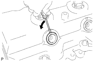 |
Using a small screwdriver, remove the nozzle holder seal by prying between the nozzle holder seal and the cutout part of the cylinder head cover.
Disconnect the ventilation hose.
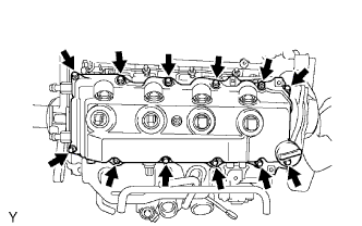 |
Remove the 10 bolts, 2 nuts, cylinder head cover and cylinder head cover gasket.
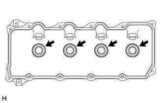 |
Remove the 4 No. 3 cylinder head cover gaskets from the cylinder head cover.
| 11. REMOVE INJECTOR ASSEMBLY |
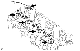 |
Remove the union bolt, 4 injector hollow screws, 5 gaskets and nozzle leakage pipe.
| *1 | Union Bolt |
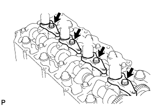 |
Remove the 4 bolts, 4 washers, 4 No. 1 nozzle holder clamps and 4 injectors.
Remove the O-ring from each injector.
Remove the 4 injection nozzle seats from the cylinder head.
| 12. REMOVE NO. 1 TIMING BELT COVER |
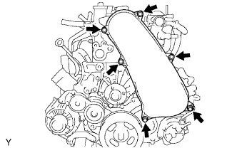 |
Remove the 6 bolts, 6 washers and timing belt cover.
| 13. REMOVE TIMING BELT |
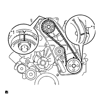 |
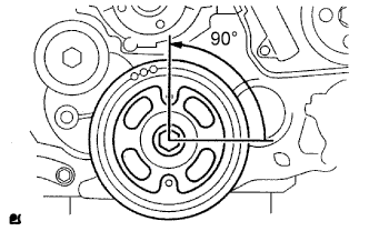
Turn the crankshaft clockwise and align the timing marks as shown in the illustration.
| *1 | Timing Mark |
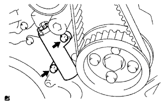 |
Uniformly loosen and remove the 2 bolts and No. 1 timing belt tensioner.
Remove the timing belt.
 |
| 14. REMOVE NO. 1 TIMING BELT IDLER SUB-ASSEMBLY |
Using a 10 mm hexagon wrench, remove the bolt, No. 1 timing belt idler and washer.
| 15. REMOVE CAMSHAFT TIMING PULLEY |
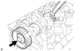 |
Remove the bolt of the camshaft timing pulley while holding the camshaft with a wrench.
Remove the camshaft timing pulley.
| 16. REMOVE NO. 2 TIMING BELT COVER |
Remove the 4 bolts, nut and timing belt cover.
| 17. REMOVE CAMSHAFT |
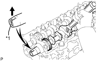 |
Turn the camshaft with a wrench so that the key groove of the camshaft faces upward.
| *1 | Key Groove |
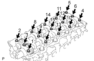 |
Uniformly loosen the 15 bearing cap bolts in several passes in the sequence shown in the illustration.
Remove the 15 bearing cap bolts, 5 bearing caps, oil seal and 2 camshafts.