 |
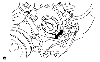
Check that the injection gear in the timing gear case moves back and forth smoothly.
ENGINE UNIT > INSTALLATION |
| 1. INSTALL FRONT NO. 1 ENGINE MOUNTING BRACKET LH |
Install the front No. 1 engine mounting bracket with the 4 bolts.
| 2. INSTALL FRONT NO. 1 ENGINE MOUNTING BRACKET RH |
Install the front No. 1 engine mounting bracket with the 4 bolts.
| 3. INSTALL ENGINE COOLANT TEMPERATURE SENSOR |
Install a new gasket to the engine coolant temperature sensor.
Install the engine coolant temperature sensor.
Connect the engine coolant temperature sensor connector.
| 4. INSTALL CAMSHAFT POSITION SENSOR |
Apply a light coat of engine oil to the O-ring of the camshaft position sensor.
Install the camshaft position sensor with the bolt.
Connect the camshaft position sensor connector.
| 5. INSTALL CRANKSHAFT POSITION SENSOR |
Apply a light coat of engine oil to the O-ring of the crankshaft position sensor.
Install the crankshaft position sensor with the bolt.
Install the 3 clips and connect the crankshaft position sensor connector.
| 6. INSTALL VANE PUMP ASSEMBLY |
Install a new O-ring to the vane pump.
Install the vane pump with the 2 nuts.
| 7. INSTALL VACUUM PUMP ASSEMBLY |
Install 2 new O-rings to the vacuum pump.
Install the vacuum pump with the 2 nuts.
| 8. INSTALL OIL COOLER COVER SUB-ASSEMBLY |
Install a new gasket and the oil cooler cover with the 13 bolts.
Connect the No. 2 vacuum transmitting pipe with the 2 nuts.
Connect the oil pressure switch connector.
| 9. INSTALL FUEL SUPPLY PUMP ASSEMBLY |
|
Check that the injection gear in the timing gear case moves back and forth smoothly.
Install a new O-ring to the fuel supply pump.
Apply a light coat of engine oil to the O-ring.
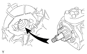 |
Align the groove of the injection gear with the set key on the drive shaft.
Install the fuel supply pump with the 2 nuts.
Install a new O-ring before tightening the set nut.
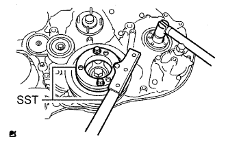 |
Using SST, hold the crankshaft pulley and install the set nut.
Install the pump drive shaft pulley and No. 2 camshaft timing pulley flange with the 4 bolts.
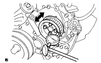 |
Move the pump drive shaft pulley back and forth to check the thrust clearance of the injection pump drive shaft.
Connect the fuel temperature sensor connector and suction control valve connector to the fuel supply pump.
Connect the 2 fuel hoses.
| 10. INSTALL COMMON RAIL ASSEMBLY |
Install the common rail with the 2 bolts.
Connect the 2 connectors.
| 11. INSTALL OIL FILTER SUB-ASSEMBLY |
Check and clean the oil filter installation surface.
Apply clean engine oil to the gasket of a new oil filter.
Lightly screw the oil filter into place by hand. Tighten it until the gasket contacts the seat.
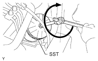 |
Using SST, tighten the oil filter. Depending on the space available, choose from the following.
If enough space is available, use a torque wrench to tighten the oil filter.
If enough space is not available to use a torque wrench, tighten the oil filter 3/4 of a turn by hand or with a common wrench.
| 12. INSTALL FUEL INLET PIPE SUB-ASSEMBLY |
Temporarily install the fuel inlet pipe with the union nuts.
Using a 17 mm union nut wrench, tighten the fuel inlet pipe union nut on the common rail side.
Using a 17 mm union nut wrench, tighten the fuel inlet pipe union nut on the fuel supply pump side.
| 13. INSTALL GLOW PLUG ASSEMBLY |
| 14. INSTALL INTAKE MANIFOLD |
| 15. INSTALL DIESEL THROTTLE BODY ASSEMBLY |
Install a new gasket and the diesel throttle body with the 2 bolts and 2 nuts.
Connect the 2 connectors.
| 16. INSTALL WATER OUTLET |
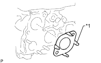 |
Install a new gasket to the cylinder head as shown in the illustration.
| *1 | Claw |
Install the water outlet with the 2 bolts.
| 17. INSTALL THERMOSTAT |
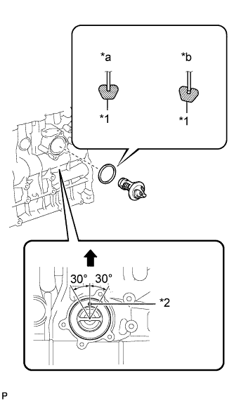 |
Install a new gasket to the thermostat.
| *1 | Gasket |
| *2 | Jiggle Valve |
| *a | CORRECT |
| *b | INCORRECT |
 | Upward |
Insert the thermostat into the cylinder block with the jiggle valve facing straight upward.
| 18. INSTALL WATER INLET |
Install the wire harness clamp bracket to the water inlet with the bolt.
Install the water inlet with the 3 bolts.
Connect the wire harness clamp.
| 19. INSTALL VENTILATION HOSE HEAT INSULATOR |
Install the ventilation hose heat insulator with the 2 bolts.
| 20. INSTALL NO. 1 COMPRESSOR MOUNTING BRACKET |
Install the No. 1 compressor mounting bracket with the 4 bolts.
| 21. INSTALL V-RIBBED BELT TENSIONER ASSEMBLY |
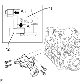 |
Install the V-ribbed belt tensioner with the 4 bolts.
| *1 | Cylinder Block |
| *2 | V-ribbed Belt Tensioner |
| 22. INSTALL GENERATOR BRACKET |
Install the generator bracket with the bolt.
| 23. INSTALL GENERATOR ASSEMBLY |
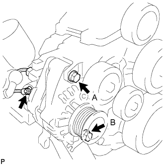 |
Install the generator with the 2 bolts.
Install the generator wire with the nut.
Connect the generator connector.
| 24. INSTALL NO. 2 IDLE PULLEY ASSEMBLY |
Install the spacer, No. 2 idle pulley and pulley plate with the bolt.
| 25. INSTALL EXHAUST MANIFOLD |
Temporarily install a new gasket, the exhaust manifold, 8 new collars and the 8 plate washers to the cylinder head with 8 new nuts.
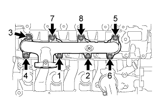 |
Tighten the 8 nuts in the order shown in the illustration.
| 26. INSTALL TURBOCHARGER SUB-ASSEMBLY |
| 27. INSTALL CRANKSHAFT PULLEY |
Align the keyway of the pulley with the key located on the crankshaft, and then slide the pulley into place to install it.
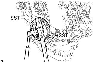 |
Using SST, install the pulley bolt.
| 28. INSTALL NO. 1 TIMING BELT IDLER SUB-ASSEMBLY |
Using a 10 mm hexagon wrench, install a new washer and the No. 1 timing belt idler with the bolt.
Check that the idler pulley moves smoothly.
If the idler pulley does not move smoothly, check the installation condition of the idler and washer.
| 29. INSTALL TIMING BELT |
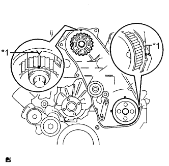 |
Check that the timing marks are aligned as shown in the illustration.
| *1 | Timing Mark |
Install the timing belt to the pump drive shaft pulley, camshaft timing pulley and No. 1 timing belt idler in sequence.
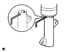 |
Place the tensioner upright. Then set a press on the top of the tensioner.
Using the press, slowly push in the push rod using 981 to 9800 N (100 to 999 kgf, 220 to 2203 lbf) of force.
Align the holes of the push rod and housing. Then pass a 1.5 mm hexagon wrench through the holes to fix the push rod in place.
Temporarily install the timing belt tensioner with the 2 bolts while pushing the idler pulley toward the timing belt.
Tighten the 2 bolts.
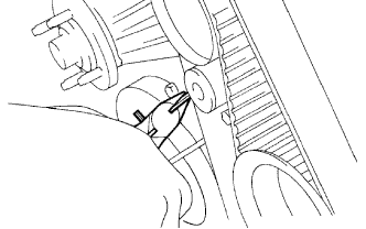 |
Remove the 1.5 mm hexagon wrench from the tensioner.
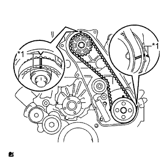 |
Turn the crankshaft clockwise 720° and check that the timing marks are aligned as shown in the illustration.
| *1 | Timing Mark |
| 30. INSTALL NO. 1 TIMING BELT COVER |
Install the timing belt cover and 6 washers with the 6 bolts.