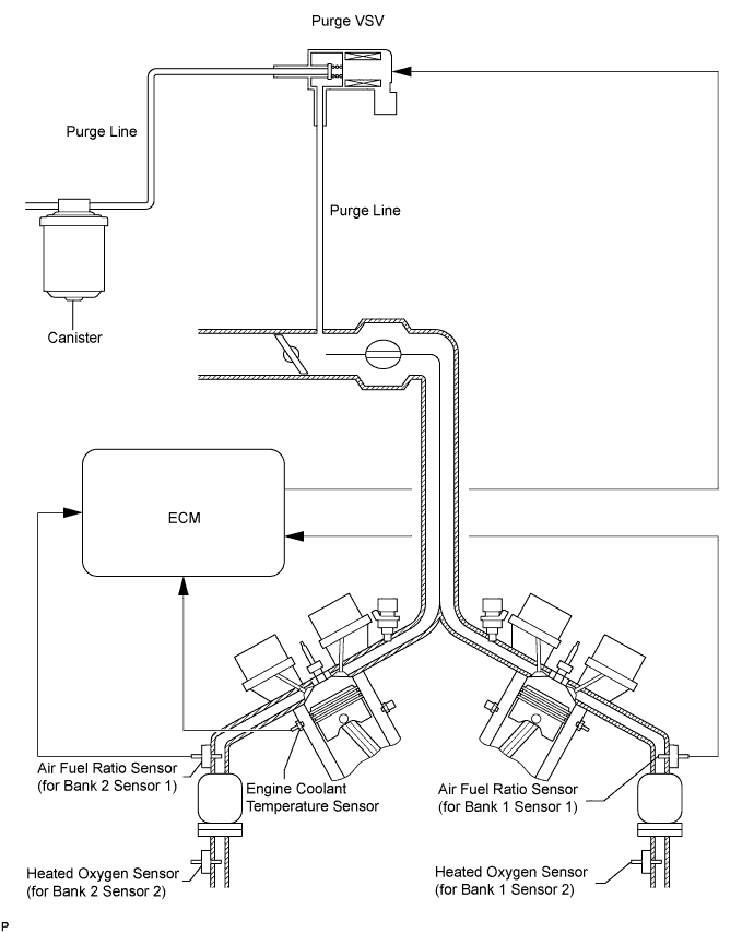
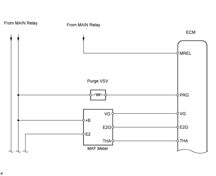
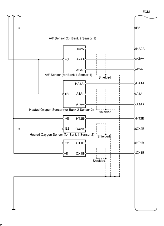
To reduce HC emissions, the following occurs. First, evaporated fuel in the fuel tank is absorbed by the charcoal canister's active carbon. Then, when the vehicle is being driven, the fuel in the canister and air are routed into the intake manifold for combustion.