 |
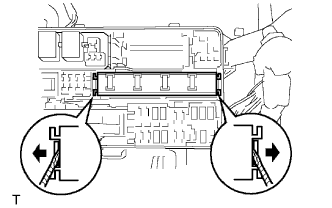
Using a screwdriver, detach the 2 claws and disconnect the integration relay from the engine room junction block.
- HINT:
- Tape the screwdriver tip before use.
INTEGRATION RELAY > ON-VEHICLE INSPECTION |
| 1. PRECAUTION |
| 2. DISCONNECT CABLE FROM NEGATIVE BATTERY TERMINAL |
| 3. REMOVE ENGINE ROOM RELAY BLOCK COVER |
| 4. CHECK INTEGRATION NO.1 RELAY |
|
Using a screwdriver, detach the 2 claws and disconnect the integration relay from the engine room junction block.
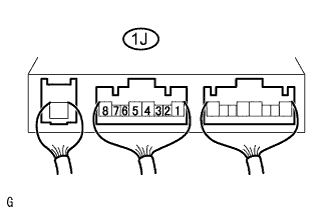 |
Measure the voltage of the C/OPN relay.
| Tester Connection | Condition | Specified Condition |
| 1J-4 - Body ground | Ignition switch ON | 10 to 14 V |
|
Measure the voltage of the MAIN relay.
| Tester Connection | Condition | Specified Condition |
| 1J-8 - Body ground | Ignition switch ON | 10 to 14 V |
| 5. INSTALL ENGINE ROOM RELAY BLOCK COVER |
| 6. CONNECT CABLE TO NEGATIVE BATTERY TERMINAL |
| 7. PERFORM INITIALIZATION |
Perform initialization (Click here).