 |
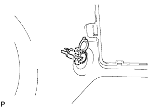
Attach the 2 claw fittings to install the socket.
POWER OUTLET SOCKET > INSTALLATION |
| 1. INSTALL REAR NO. 1 POWER OUTLET SOCKET ASSEMBLY |
|
Attach the 2 claw fittings to install the socket.
| 2. INSTALL QUARTER INSIDE TRIM BOARD LH |
Connect the power point socket connector.
Detach the 7 claws and 10 clips to install the quarter inside trim board.
Install the clip.
w/ Rear No. 2 Seat:
Connect the rear No. 2 seat outer belt floor anchor with the bolt.
Connect the rear No. 1 seat outer belt floor anchor with the bolt.
Attach the 2 claws to install the outer lap belt anchor cover.
| 3. INSTALL QUARTER TRIM HOOK |
Connect the power point socket connector.
Detach the 7 claws and 10 clips to install the quarter inside trim board.
Install the clip.
w/ Rear No. 2 Seat:
Connect the rear No. 2 seat outer belt floor anchor with the bolt.
Connect the rear No. 1 seat outer belt floor anchor with the bolt.
Attach the 2 claws to install the outer lap belt anchor cover.
| 4. INSTALL REAR DOOR OPENING TRIM WEATHERSTRIP LH |
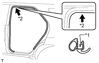 |
Align the paint mark on the rear door opening trim weatherstrip with the mark position on the vehicle and install the rear door opening trim weatherstrip as shown in the illustration.
| *1 | Paint Mark |
| *2 | Mark Position |
| 5. INSTALL REAR DOOR SCUFF PLATE LH |
Attach the 2 clips and 7 claws to install the rear door scuff plate.
| 6. INSTALL BACK DOOR SCUFF PLATE |
Attach the 4 claws, 2 guides and 6 clips to install the back door scuff plate.
| 7. INSTALL NO. 1 POWER OUTLET SOCKET ASSEMBLY |
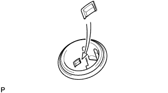 |
Align the protrusion on the backside of the socket with the groove of the cover. Then push the socket into the cover.
| 8. INSTALL SWITCH BASE |
Connect the connectors.
Attach the 9 claws and guide to install the switch base.