STARTER (for 1.4 kW Type) > INSPECTION |
| 1. INSPECT STARTER ASSEMBLY |
Mount the starter in a vise between aluminum plates.
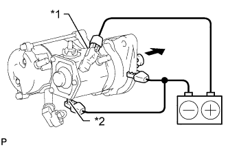
Perform a pull-in test.
Remove the nut and disconnect the lead wire from terminal C.
![]() |
Connect the battery to the magnet starter switch as shown in the illustration. Check that the clutch pinion gear moves outward.
| *1 | Terminal 50 |
| *2 | Terminal C |
![]() | Moves outward |
![]() |
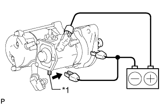
Perform a holding test.
Disconnect the negative (-) terminal lead from terminal C with the condition specified in the pull-in test above being maintained. Check that the pinion gear remains out.
| *1 | Terminal C |
![]() | Disconnect |
![]() |
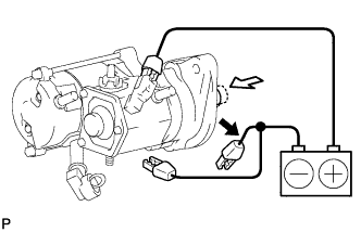
Inspect the clutch pinion gear return.
Disconnect the negative (-) terminal lead from the starter body. Check that the clutch pinion gear returns inward.
![]() | Disconnect |
![]() | Returns inward |
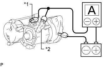
Perform an operation test without load.
Connect the lead wire to terminal C.
![]() |
Connect the battery and an ammeter to the starter as shown in the illustration.
| *1 | Terminal 30 |
| *2 | Terminal 50 |
Check that the starter rotates smoothly and steadily while the pinion gear is moving outward. Then measure the current.
| 2. INSPECT MAGNET STARTER SWITCH ASSEMBLY |
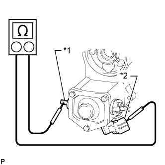
Inspect the pull-in coil.
![]() |
Measure the resistance according to the value(s) in the table below.
| Tester Connection | Condition | Specified Condition |
| Terminal 50 - Terminal C | Always | Below 1 Ω |
| *1 | Terminal C |
| *2 | Terminal 50 |
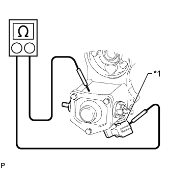
Inspect the holding coil.
![]() |
Measure the resistance according to the value(s) in the table below.
| Tester Connection | Condition | Specified Condition |
| Terminal 50 - Switch Body | Always | Below 2 Ω |
| *1 | Terminal 50 |
| 3. INSPECT BRUSH |
![]() |
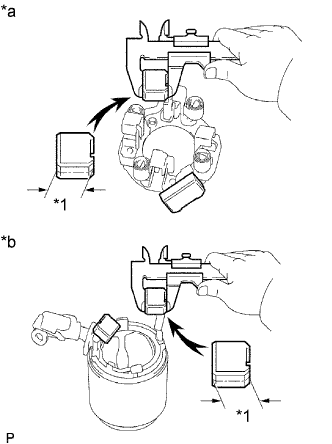
Using a vernier caliper, measure the brush length.
| *1 | Length |
| *a | Brush Holder Side |
| *b | Starter Yoke Side |
| 4. INSPECT STARTER BRUSH HOLDER ASSEMBLY |
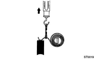
Check the brush spring load.
![]() |
Take a pull scale reading immediately after the brush spring separates from the brush.
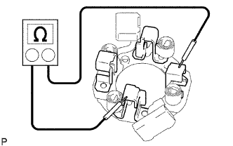
Inspect the brush insulation.
![]() |
Measure the resistance according to the value(s) in the table below.
| Tester Connection | Condition | Specified Condition |
| Positive (+) Brush Holder - Negative (-) Brush Holder | Always | 10 kΩ or higher |
| 5. INSPECT STARTER YOKE ASSEMBLY |
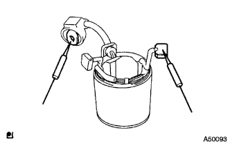
Inspect the field coil for an open circuit.
![]() |
Measure the resistance according to the value(s) in the table below.
| Tester Connection | Condition | Specified Condition |
| Lead Wire - Brush | Always | Below 1 Ω |
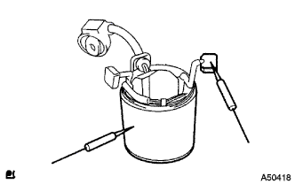
![]() |
Measure the resistance according to the value(s) in the table below.
| Tester Connection | Condition | Specified Condition |
| Starter Yoke Body - Brush | Always | 10 kΩ or higher |
| 6. INSPECT STARTER ARMATURE ASSEMBLY |
Check the commutator for dirt and/or burns on the surface.
If the surface is dirty or burnt, correct it with sandpaper (No. 400) or a lathe.
![]() |
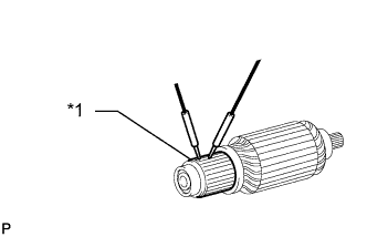
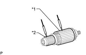
Inspect the commutator for an open circuit.
Measure the resistance according to the value(s) in the table below.
| Tester Connection | Condition | Specified Condition |
| Segment - Segment | Always | Below 1 Ω |
| *1 | Segment |
Inspect the commutator for a short circuit.
![]() |
Measure the resistance according to the value(s) in the table below.
| Tester Connection | Condition | Specified Condition |
| Segment - Coil Core | Always | 10 kΩ or higher |
| *1 | Coil Core |
| *2 | Segment |
![]() |
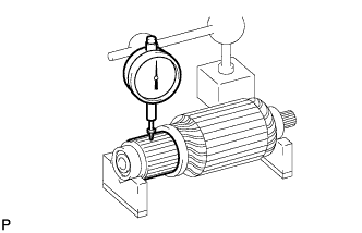
Check the commutator circle runout.
Place the commutator on V-blocks.
Using a dial indicator, measure the circle runout.
![]() |
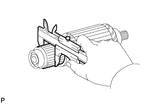
Using a vernier caliper, measure the commutator diameter.
![]() |
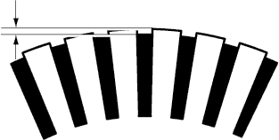
Using a vernier caliper, measure the undercut depth of the commutator.
| 7. INSPECT STARTER CLUTCH SUB-ASSEMBLY |
![]() |
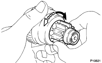
Rotate the pinion gear clockwise and check that it turns freely. Try to rotate the pinion gear counterclockwise and check that it locks.
![]() | Free |
![]() | Lock |
Turn the pinion gear by hand while applying inward force and check the movement of the bearing.
If resistance is felt or the bearing sticks, replace the starter clutch sub-assembly.