 |
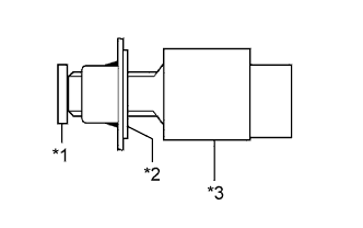
Install the stop light switch to the adjuster until the switch body slightly touches the brake pedal.
| *1 | Brake Pedal |
| *2 | Adjuster |
| *3 | Stop Light Switch Assembly |
- NOTICE:
- Do not depress the pedal.
STOP LIGHT SWITCH > INSTALLATION |
| 1. INSTALL STOP LIGHT SWITCH ASSEMBLY |
|
Install the stop light switch to the adjuster until the switch body slightly touches the brake pedal.
| *1 | Brake Pedal |
| *2 | Adjuster |
| *3 | Stop Light Switch Assembly |
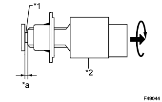 |
Rotate the stop light switch assembly clockwise so that the clearance is between 1.5 to 2.5 mm (0.0590 to 0.0984 in.) as shown in the illustration.
| *1 | Shaft |
| *2 | Stop Light Switch Assembly |
| *a | 1.5 to 2.5 mm |
Check the stop light switch clearance.
Connect the connector.
| 2. CONNECT CABLE TO NEGATIVE BATTERY TERMINAL |
| 3. PERFORM INITIALIZATION |
Perform initialization (Click here).