| NG |  |
| Go to step 3 |
DTC P0011 Camshaft Position "A" - Timing Over-Advanced or System Performance (Bank 1) |
DTC P0012 Camshaft Position "A" - Timing Over-Retarded (Bank 1) |
| DTC No. | DTC Detection Condition | Trouble Area |
| P0011 | Advanced cam timing: After engine is warmed up, valve timing does not change from current valve timing while driving at engine speed of 500 to 4,000 rpm (1 trip detection logic) |
|
| P0012 | Retarded cam timing: After engine is warmed up, valve timing does not change from current valve timing while driving at engine speed of 500 to 4,000 rpm (2 trip detection logic) |
|
| Advanced timing over (valve timing is out of specified range) | P0011 |
| Retarded timing over (valve timing is out of specified range) | P0012 |
| 1.PERFORM ACTIVE TEST (OPERATE OCV) |
Start and warm up the engine.
Turn the ignition switch OFF.
Connect the intelligent tester to the DLC3.
Turn the ignition switch ON and turn the tester ON.
Enter the following menus: Powertrain / Engine and ECT / Active Test / VVT Control (Bank 1).
Using the intelligent tester, operate the OCV and check the engine speed.
| Tester Operation | Specified Condition |
| OCV is OFF | Normal engine speed |
| OCV is ON | Rough idle or engine stall |
|
| ||||
| OK | |
 |
| 2.CHECK IF DTC OUTPUT RECURS (DTC P0011 OR P0012) |
Clear the DTCs using the intelligent tester (Click here).
Start the engine and warm it up.
Drive the vehicle for 10 minutes or more.
Read output DTC using the intelligent tester.
|
| ||||
| NG | |
|
| 3.CHECK VALVE TIMING |
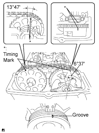 |
Remove the cylinder head cover.
Turn the crankshaft to align the timing marks of the crankshaft.
Align the groove of the crankshaft pulley with the "0" position.
Confirm whether the timing marks of the camshaft pulley and cylinder head cover are facing each other.
If the timing marks are not facing each other, turn the crankshaft clockwise 360°. Confirm again if the timing marks are facing each other.
|
| ||||
| OK | |
|
| 4.CHECK ECM (OCV SIGNAL) |
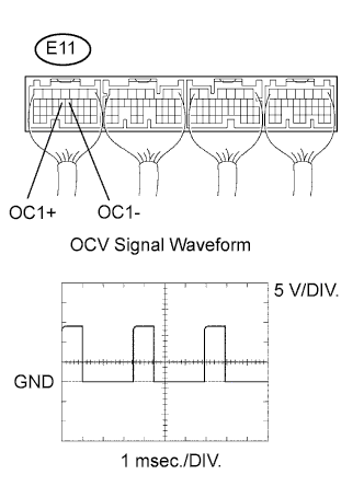 |
While idling, check the waveform the ECM connector using an oscilloscope.
| Tester Connection | Specified Condition |
| E11-13 (OC1+) - E11-12 (OC1-) | Correct waveform is as shown |
| Tool Setting | Condition |
| 5 V/DIV., 1 msec./DIV. | Accelerate slowly after engine warm-up |
|
| ||||
| OK | |
|
| 5.CHECK OIL CONTROL VALVE FILTER |
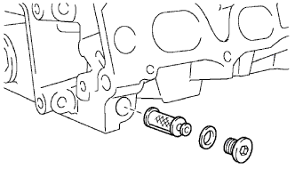 |
Remove the OCV filter.
Check that the filter is not clogged.
|
| ||||
| OK | |
|
| 6.INSPECT CAMSHAFT TIMING OIL CONTROL VALVE ASSEMBLY (OCV) |
Measure the resistance between the terminals of the OCV.
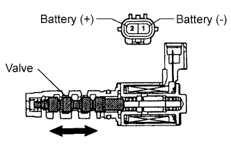 |
Remove the OCV.
Apply positive (+) battery voltage of terminal 2 and negative (-) battery voltage to terminal 1 and check the valve operation.
|
| ||||
| NG | |
|
| 7.REPLACE CAMSHAFT TIMING OIL CONTROL VALVE ASSEMBLY (OCV) |
| NEXT | |
|
| 8.CHECK CAMSHAFT TIMING GEAR ASSEMBLY |
|
| ||||
| NG | |
|
| 9.REPLACE CAMSHAFT TIMING GEAR ASSEMBLY |
| NEXT | |
|
| 10.CHECK FOR BLOCKAGE (OCV, OIL CHECK VALVE, OIL HOLE) |
|
| ||||
| OK | |
|
| 11.CHECK IF DTC OUTPUT RECURS (DTC P0011 OR P0012) |
Clear the DTCs using the intelligent tester (Click here).
Start the engine and warm it up.
Drive the vehicle for 10 minutes or more.
Read output DTC using the intelligent tester.
|
| ||||
| NG | ||
 | ||
| ||
