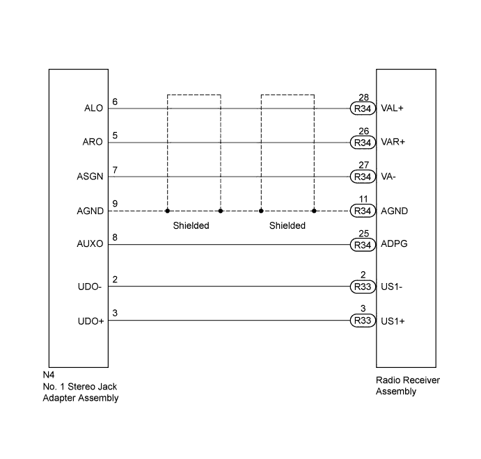
AUDIO AND VISUAL SYSTEM (for Radio Receiver Type) > Sound Signal Circuit between Radio Receiver and Stereo Jack Adapter |
| 1.CHECK HARNESS AND CONNECTOR (RADIO RECEIVER - STEREO JACK ADAPTER) |
Disconnect the R34 and R33 radio receiver assembly connectors.
Disconnect the N4 No. 1 stereo jack adapter assembly connector.
Measure the resistance according to the value(s) in the table below.
| Tester Connection | Condition | Specified Condition |
| R34-28 (VAL+) - N4-6 (ALO) | Always | Below 1 Ω |
| R34-26 (VAR+) - N4-5 (ARO) | ||
| R34-27 (VA-) - N4-7 (ASGN) | ||
| R34-11 (AGND) - N4-9 (AGND) | ||
| R34-25 (ADPG) - N4-8 (AUXO) | ||
| R33-2 (US1-) - N4-2 (UDO-) | ||
| R33-3 (US1+) - N4-3 (UDO+) | ||
| R34-28 (VAL+) - Body ground | Always | 10 kΩ or higher |
| R34-26 (VAR+) - Body ground | ||
| R34-27 (VA-) - Body ground | ||
| R34-11 (AGND) - Body ground | ||
| R34-25 (ADPG) - Body ground | ||
| R33-2 (US1-) - Body ground | ||
| R33-3 (US1+) - Body ground |
|
| ||||
| OK | ||
 | ||
| ||
