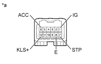
Tester Connection
| Condition
| Specified Condition
|
6 (ACC) - 8 (E)
| Ignition switch ON
| 10 to 14 V
|
Ignition switch ACC
| 10 to 14 V
|
Ignition switch off
| Below 1 V
|
7 (STP) - 8 (E)
| Brake pedal depressed
| 10 to 14 V
|
Brake pedal released
| Below 1 V
|
12 (KLS+) - 8 (E)
| 1. Ignition switch ACC and shift lever in P
| Below 1 V
|
2. Ignition switch ACC and shift lever not in P (Within approx. 1 second)
| 7.5 to 11 V
|
3. Ignition switch ACC and shift lever not in P (After approx. 2 seconds)
| 6 to 9 V
|
1 (IG) - 8 (E)
| Ignition switch ON
| 10 to 14 V
|
Ignition switch off
| Below 1 V
|
8 (E) - Body ground
| Always
| Below 1 Ω
|