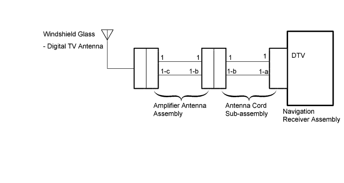
DTC B15C8 Digital TV Antenna 1 Disconnected |
| DTC No. | DTC Detection Condition | Trouble Area |
| B15C8 | Television antenna assembly is not connected. |
|
| 1.CHECK FOR DTC |
Clear the DTCs (Click here).
Recheck for DTCs and check that no DTCs are output (Click here).
|
| ||||
| OK | ||
 | ||
| ||
| 2.CHECK ANTENNA CORD SUB-ASSEMBLY |
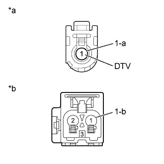 |
Disconnect the navigation receiver assembly connector.
Disconnect the antenna connector from the amplifier antenna assembly.
Measure the resistance according to the value(s) in the table below.
| Tester Connection | Condition | Specified Condition |
| 1 (DTV) - 1 | Always | Below 1 Ω |
| 1-a - 1-b | Always | Below 1 Ω |
| 1 (DTV) - Body ground | Always | 10 kΩ or higher |
| 1-a - Body ground | Always | 10 kΩ or higher |
| *a | Front wire of wire harness connector (to Navigation Receiver Assembly) |
| *b | Front wire of wire harness connector (to Amplifier Antenna Assembly) |
|
| ||||
| OK | |
 |
| 3.CHECK AMPLIFIER ANTENNA ASSEMBLY |
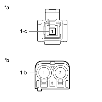 |
Disconnect the antenna connector from the antenna cord sub-assembly.
Disconnect the antenna connector from the windshield glass (digital TV antenna).
Measure the resistance according to the value(s) in the table below.
| Tester Connection | Condition | Specified Condition |
| 1 - 1 | Always | Below 1 Ω |
| 1-b - 1-c | Always | Below 1 Ω |
| 1 - Body ground | Always | 10 kΩ or higher |
| 1-b - Body ground | Always | 10 kΩ or higher |
| *a | Front wire of wire harness connector (to Windshield Glass [Digital TV Antenna]) |
| *b | Front wire of wire harness connector (to Antenna Cord Sub-assembly) |
|
| ||||
| OK | |
|
| 4.CHECK WINDSHIELD GLASS (DIGITAL TV ANTENNA) |
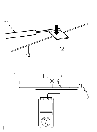 |
Check for continuity in the antenna.
| *1 | Tester Probe |
| *2 | Tin Foil |
| *3 | Antenna Wire |
|
| ||||
| OK | |
|
| 5.CHECK WINDSHIELD GLASS (DIGITAL TV ANTENNA) |
Replace the windshield glass (digital TV antenna) with a known good one and check if the same DTC is output again (Click here).
Clear the DTCs (Click here).
Recheck for DTCs and check if the same DTC is output again (Click here).
|
| ||||
| OK | ||
| ||
| ||

