BM33K0E
_01
Vehicle Exterior
_046210
BODY WELD POINT
_0223733
REAR FLOOR SIDE CENTER MEMBER
F
BODY WELD POINT REAR FLOOR SIDE CENTER MEMBER CUT AND JOIN REPLACEMENT SECTIONS
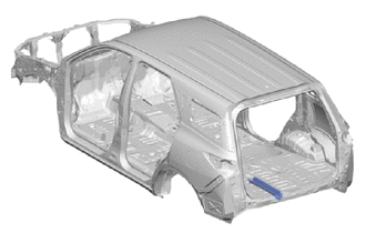
With the body lower back panel cut and join replacement sections (small areas) removed.
REMOVAL
| Symbol Meaning | |
|---|---|

|
Remove Weld Points |

|
Remove Weld Points |

|
Cut and Join Location |
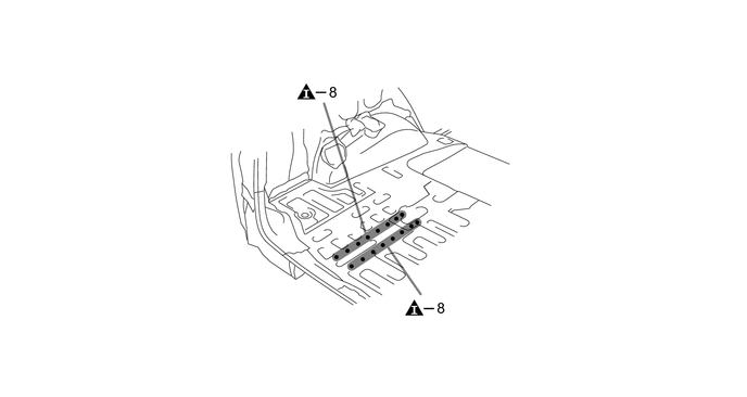
a.
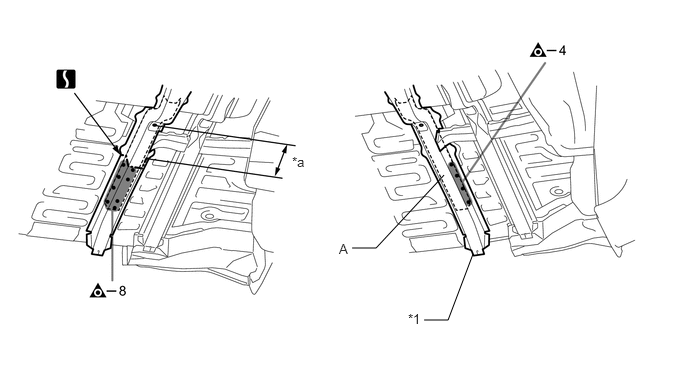
Carefully cut the rear floor side center member so not to damage A.
3.667,2.583 3.917,2.583
3.917,2.583 4.625,1.823
false
4.417,3.333 4.667,3.333
4.667,3.333 4.927,2.646
false
3.042,1.604 3.354,1.76
0.313,0.156
10
false
*a
4.25,3.24 4.563,3.396
0.313,0.156
10
false
*1
3.531,2.51 3.844,2.667
0.313,0.156
10
false
A
| *a | 270 mm (10.63 in.) | - | - |
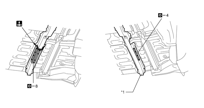
| *1 | REAR FLOOR SIDE CENTER MEMBER | - | - |
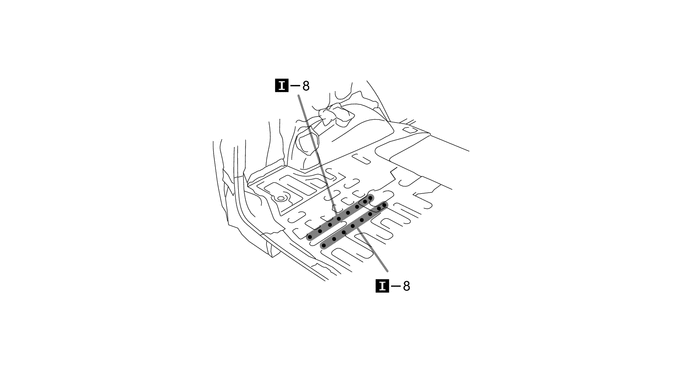
INSTALLATION
| Symbol Meaning | |
|---|---|

|
Plug Weld |

|
Plug Weld |

|
Butt Weld |
4.417,3.25 4.667,3.25
4.667,3.25 4.938,2.646
false
4.25,3.167 4.563,3.323
0.313,0.156
10
false
*1
| *1 | REAR FLOOR SIDE CENTER MEMBER | - | - |
a.
After welding, apply body sealer and undercoating to the corresponding parts. (See the painting/coating)
b.
After applying the top coat, apply anti-rust agent to the internal panel portion of the closed section structural weld points.