BM33K0E
_01
Vehicle Exterior
_046210
BODY WELD POINT
_0223738
CAB MOUNTING NO.2 BRACKET
F
BODY WELD POINT CAB MOUNTING NO.2 BRACKET ASSEMBLY REPLACEMENT
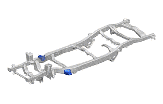
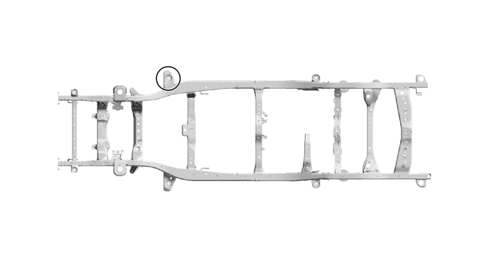
- HINT:
- ·
Use the same procedure for the RH and LH.
·The procedure listed below is for the RH.
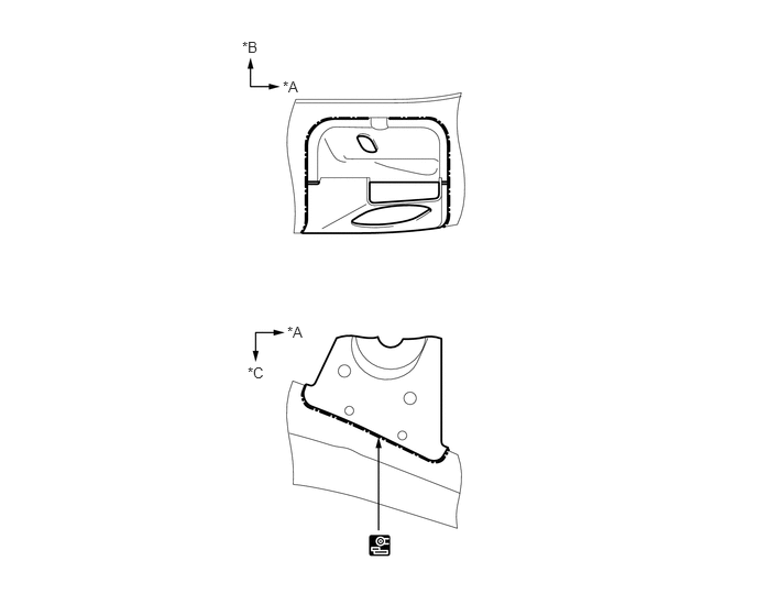
REMOVAL
| Symbol Meaning | |
|---|---|

|
Cut with Disc Sander etc. |
2.719,3.063 3.031,3.219
0.313,0.156
10
false
*A
2.292,0.365 2.604,0.521
0.313,0.156
10
false
*B
2.677,0.74 2.99,0.896
0.313,0.156
10
false
*A
2.344,3.448 2.656,3.604
0.313,0.156
10
false
*C
| *A | FRONT | *B | UPPER |
| *C | LH | - | - |
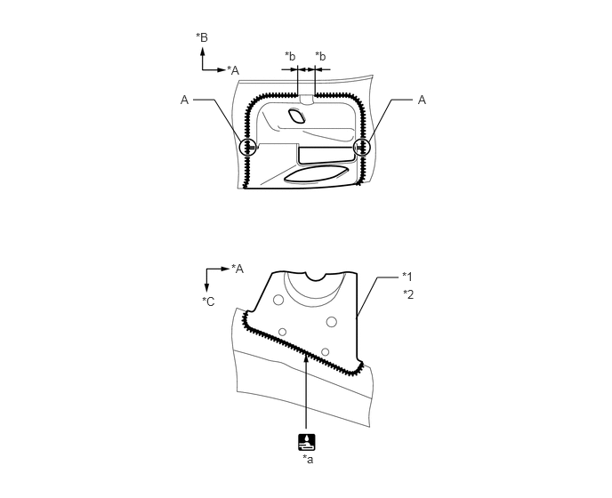
INSTALLATION
| Symbol Meaning | |
|---|---|

|
Fillet Weld |
a.
Temporarily install the new parts and measure each part of the new parts in accordance with the body dimension diagram. (See the body dimensions)
b.
Make sure that proper welding can be performed by setting up the welding conditions as necessary before performing work.
c.
Before installing the upper body, confirm the alignment of the upper body and frame.
d.
To prevent heat deformation, weld the right and left side of each part before continuing to the next part.
e.
Make sure that the welding bead at A is overlapped.
4.313,1.677 4.583,1.167
4.583,1.167 4.833,1.167
false
2.823,1.667 2.51,1.167
2.51,1.167 2.26,1.167
false
4.167,3.74 4.417,3.25
4.417,3.25 4.667,3.25
false
2.708,3.063 3.021,3.219
0.313,0.156
10
false
*A
3.688,0.573 4,0.729
0.313,0.156
10
false
*b
2.656,0.74 2.969,0.896
0.313,0.156
10
false
*A
2.292,0.354 2.604,0.51
0.313,0.156
10
false
*B
2.365,3.448 2.677,3.604
0.313,0.156
10
false
*C
4.708,3.156 5.021,3.313
0.313,0.156
10
false
*1
3.542,5.292 3.854,5.448
0.313,0.156
10
false
*a
3.333,0.573 3.646,0.729
0.313,0.156
10
false
*b
2.115,1.083 2.427,1.24
0.313,0.156
10
false
A
4.896,1.083 5.208,1.24
0.313,0.156
10
false
A
4.719,3.365 5.031,3.521
0.313,0.156
10
false
*2
| *A | FRONT | *B | UPPER |
| *C | LH | - | - |
| *1 | CAB MOUNTING BRACKET SUB-ASSEMBLY NO.2 (LH) | *2 | CAB MOUNTING BRACKET SUB-ASSEMBLY (RH) |
| *a | 591 mm (23.27 in.) | *b | 0 +/- 5 mm (0 +/- 0.20 in.) |
f.
After applying the top coat, apply anti-rust agent to the internal panel portion of the closed section structural weld points.