Home › Engine / Hybrid System › 2TR-FE ENGINE CONTROL › SFI SYSTEM
NM33K0E _51 Engine / Hybrid System _045489 2TR-FE ENGINE CONTROL _0213939 SFI SYSTEM DE DETAILS F

2TR-FE ENGINE CONTROL  SFI SYSTEM  DETAILS  AIR FUEL RATIO SENSOR AND HEATED OXYGEN SENSOR  


CONSTRUCTION


a.

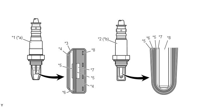
A planar type air fuel ratio sensor and a cup type oxygen sensor are used. The basic construction of the oxygen sensor and the air fuel ratio sensor is the same. However, they are divided into the planar type and cup type, in accordance with the different types of heater construction used.


b.

The planar type air fuel ratio sensor uses alumina, which excels in heat conductivity and electrical insulation, to integrate the sensor element with the heater, thus improving the warmup performance of the sensor.


c.

The cup type oxygen sensor contains a sensor element that surrounds the heater.
W126170C01
3.885,1.438 4.177,1.552 true 0.823,1.396 1.115,1.51 true 2.958,1.896 3.229,1.823 true 2.792,2.396 3.188,2.49 true 2.729,2.563 3.188,2.75 true 2.969,2.958 3.188,3.063 true 2.646,3.188 2.375,3.302 true 2.573,2.448 2.229,2.365 true 2.438,1.969 2.24,1.813 true 2.542,1.875 2.417,1.625 true 5.396,1.781 5.198,1.531 true 5.469,1.781 5.333,1.448 true 5.563,1.76 5.531,1.427 true 5.635,1.75 5.688,1.427 true 5.865,1.76 5.979,1.438 true 5.958,1.26 6.271,1.417 0.313,0.156 10 false *8 5.656,1.229 5.969,1.385 0.313,0.156 10 false *7 0.417,1.25 1.042,1.521 0.625,0.271 10 false *1 (*a) 3.49,1.302 3.948,1.542 0.458,0.24 10 false *2 (*b) 2.302,1.458 2.615,1.615 0.313,0.156 10 false *3 2.083,1.656 2.396,1.813 0.313,0.156 10 false *4 5.438,1.24 5.75,1.396 0.313,0.156 10 false *5 5.219,1.271 5.531,1.427 0.313,0.156 10 false *6 5.063,1.375 5.375,1.531 0.313,0.156 10 false *5 3.26,1.698 3.573,1.854 0.313,0.156 10 false *8 2.073,2.24 2.385,2.396 0.313,0.156 10 false *5 3.229,2.406 3.542,2.563 0.313,0.156 10 false *7 3.24,2.688 3.552,2.844 0.313,0.156 10 false *5 3.219,2.99 3.531,3.146 0.313,0.156 10 false *4 2.219,3.208 2.531,3.365 0.313,0.156 10 false *6
*1 Air Fuel Ratio Sensor (Bank 1, Sensor 1) *2 Oxygen Sensor (Bank 1, Sensor 2)
*3 Diffusion Resistance Layer *4 Alumina
*5 Platinum Electrode *6 Sensor Element (Zirconia)
*7 Atmosphere *8 Heater
*a Planar Type *b Cup Type


d.

As illustrated below, the conventional oxygen sensor is characterized by a sudden change in its output voltage at the threshold of the stoichiometric air fuel ratio (14.7:1). In contrast, the air fuel ratio sensor data is approximately proportionate to the existing air fuel ratio. The air fuel ratio sensor converts the oxygen density to current and sends it to the ECM. As a result, the detection precision of the air fuel ratio has been improved. The air fuel ratio sensor data can be viewed using the Global TechStream (GTS).
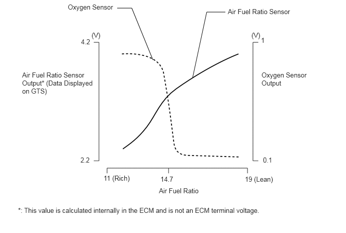
Characteristics of Air Fuel Ratio Sensor and Oxygen Sensor
W100042E76
2.427,0.167 2.729,0.167 2.729,0.167 3.167,1.24 false 4.667,0.25 4.281,0.25 4.281,0.25 3.99,1.604 false 2.146,3.604 2.76,3.927 0.615,0.323 10 false 11 (Rich) 5.073,3.625 5.76,3.979 0.688,0.354 10 false 19 (Lean) 3.323,3.625 3.625,3.885 0.302,0.26 10 false 14.7 3.292,3.865 4.24,4.198 0.948,0.333 10 false Air Fuel Ratio 5.208,0.646 5.438,0.844 0.229,0.198 10 false (V) 1.896,0.646 2.125,0.844 0.229,0.198 10 false (V) 5.406,0.75 5.552,0.948 0.146,0.198 10 false 1 5.448,3.229 5.688,3.427 0.24,0.198 10 false 0.1 1.667,3.229 1.938,3.521 0.271,0.292 10 false 2.2 1.677,0.781 1.948,0.958 0.271,0.177 10 false 4.2 5.417,1.469 6.49,2.146 1.073,0.677 10 false Oxygen Sensor Output 0.458,1.469 1.938,2.719 1.479,1.25 10 false Air Fuel Ratio Sensor Output* (Data Displayed on GTS) 4.719,0.156 6.115,0.417 1.396,0.26 10 false Air Fuel Ratio Sensor 0.375,4.271 5.844,4.604 5.469,0.333 10 false *: This value is calculated internally in the ECM and is not an ECM terminal voltage. 1.406,0.063 2.427,0.292 1.021,0.229 10 false Oxygen Sensor