HEATING / AIR CONDITIONING AIR CONDITIONING SYSTEM DETAILS SERVO MOTOR
CONSTRUCTION
Servo Motor
On models with an automatic air conditioning system, individual servo motors are used for the fresh/recirculation damper, the mode control damper and the air mix control dampers.
On models with manual air conditioning system, the fresh/recirculation damper servo motor is used.
A No. 1 air conditioning radiator damper servo sub-assembly that combines 2 types of servo motors (for the mode control damper and for the air mix control damper) is used.
The servo motors are pulse pattern type servo motors, which perform control by communicating over the bus wire with the air conditioning amplifier assembly. Along with using pulse pattern type servo motors, smart connectors contain ICs that have such functions as communicating with the air conditioning amplifier assembly.
The installation positions for the damper servo motors are on the side of the blower assembly for the No. 1 blower damper servo sub-assembly, and on the side of the air conditioning unit assembly for the No. 1 air conditioning radiator damper servo sub-assemblies.
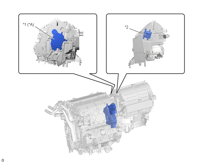
| *A | Models with Automatic Air Conditioning System | - | - |
| *1 | No. 1 Air Conditioning Radiator Damper Servo Sub-assembly
·
Mode Switching Damper Servo Motor ·
Air Mix Damper Servo Motor |
*2 | No. 1 Blower Damper Servo Sub-assembly (Fresh/Recirculation Damper Servo Motor) |
Pulse Pattern Type Servo Motor (Models with Automatic Air Conditioning System)
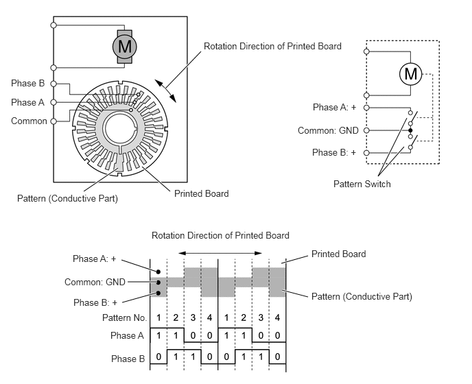
In contrast to the previous type that detects the position by way of potentiometer voltage, the pulse pattern type servo motor detects the relative position by way of 2-bit on/off signals.
The forward and reverse revolutions of this motor are detected by way of 2 phases, A and B, which output 4 types of patterns. The air conditioning amplifier assembly counts the number of pulse patterns in order to determine the stopped position.