Home › Vehicle Exterior › EXTERIOR PANELS / TRIM › BODY STRUCTURE
NM33K0E _59 Vehicle Exterior _047716 EXTERIOR PANELS / TRIM _0226895 BODY STRUCTURE DE DETAILS F

EXTERIOR PANELS / TRIM  BODY STRUCTURE  DETAILS  AERODYNAMICS  


CONSTRUCTION


a.

Aerodynamic Parts

i.

Aerodynamic parts are provided on various parts of the vehicle and the Cd level* is reduced to achieve improved fuel efficiency.

HINT:

*: The Cd level refers to the air resistance coefficient. Cd stands for Constant drag. The lower the level is, the lesser the air resistance is. This improves fuel efficiency.


·

A front wheel opening extension pad No. 1 (*1 in illustration) and step panel RR (*4 in illustration) are provided to restrain the air volume that contacts the rotating tire. As a result, disturbances due to air turbulence from the rotation of the front tire interfering with the air flow around it are suppressed and the air flow is adjusted to ensure a higher dimension of straightline stability when driving at high speeds while reducing air resistance.

·

Models with front spoiler, the front spoiler (*2 and *3 in illustration) directs air flow away from the underbody to over the smooth body therefore reducing drag.

·

Models with front spoiler, the front spoiler (*2 and *3 in illustration) adds downforce which increases vehicle stability.
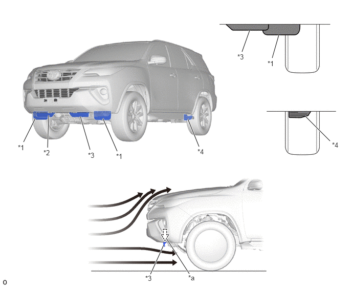
Spats and Spoiler (The illustration shows an example)
V113808C01
5.542,1.177 5.677,0.708 true 4.927,1.052 5.083,0.615 true 6.719,2.865 6.219,2.365 true 4.052,2.979 3.823,2.417 true 2.385,3.073 2.094,2.406 true 1.833,3.042 1.635,2.365 true 0.969,3 0.99,2.344 true 0.479,2.885 0.719,2.406 true 3.333,4.979 3.063,5.573 true 3.854,5.563 3.385,4.844 true 5.448,1.208 5.656,1.438 0.208,0.229 10 false *1 4.833,1.073 5.042,1.302 0.208,0.229 10 false *3 0.365,2.917 0.573,3.146 0.208,0.229 10 false *1 0.885,3.021 1.094,3.25 0.208,0.229 10 false *2 1.792,3.073 2,3.302 0.208,0.229 10 false *3 2.365,3.094 2.573,3.323 0.208,0.229 10 false *1 4.021,3 4.229,3.229 0.208,0.229 10 false *4 6.76,2.865 6.969,3.094 0.208,0.229 10 false *4 2.958,5.573 3.167,5.802 0.208,0.229 10 false *3 3.833,5.563 4.042,5.792 0.208,0.229 10 false *a
*1 Front Wheel Opening Extension Pad No. 1 *2 Front Spoiler RH
*3 Front Spoiler LH *4 Step Panel RR
*a Downforce - -
V100135

Airflow - -


·

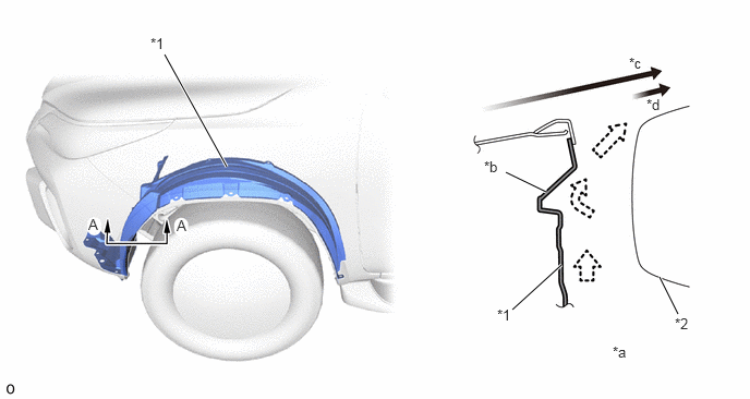
An aerodynamics bead is provided in the front fender splash shield sub-assembly (*1 in illustration). As a result, airflow in the wheel housing is introduced to smoothly flow parallel to the tires to make it flow in the wheel housing smoothly, thus ensuring superior maneuver stability.
V113809C01
2.167,1.594 1.573,0.521 true 5.219,1.833 4.833,1.646 true 5.365,2.531 4.896,2.958 true 6.302,2.646 6.479,3 true 1.438,0.333 1.729,0.552 0.292,0.219 10 false *1 0.844,2.063 1.135,2.281 0.292,0.219 10 false A 6.01,0.521 6.302,0.74 0.292,0.219 10 false *c 6.177,0.917 6.469,1.125 0.292,0.208 10 false *d 4.625,1.51 4.917,1.719 0.292,0.208 10 false *b 4.75,2.927 5.042,3.135 0.292,0.208 10 false *1 6.448,3.01 6.74,3.219 0.292,0.208 10 false *2 5.854,3.281 6.146,3.49 0.292,0.208 10 false *a 1.688,2.073 1.979,2.292 0.292,0.219 10 false A
*1 Front Fender Splash Shield Sub-assembly *2 Front Tire
*a A - A Cross Section *b Aerodynamics Bead
*c Airflow from Front of Vehicle *d Airflow from Inside of Vehicle


·

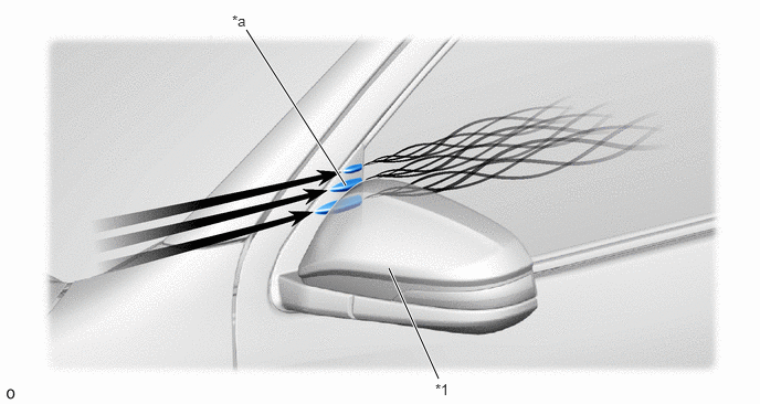
The outer rear view mirror assembly uses an aero stabilizing fin to adjust airflow and ensure superior driving stability.
V113709C02
3.26,1.75 2.323,0.281 true 3.667,2.531 4.135,3.573 true 2.188,0.115 2.49,0.385 0.302,0.271 10 false *a 4.104,3.594 4.385,3.792 0.281,0.198 10 false *1
*1 Outer Rear View Mirror Assembly - -
*a Aero Stabilizing Fin - -
V100135

Airflow - -


·

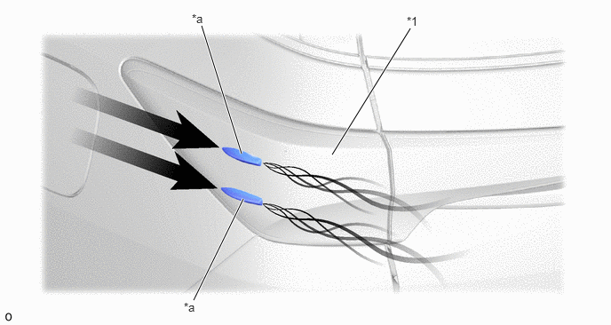
An aero stabilizing fin is provided on the rear combination lamp assembly and a type of aerodynamic technology known a vortex generator is used for the fin. Small vortexes are purposely generated in airflow to push the vehicle from the left and right sides, thus achieving excellent operation stability.
V113810C01
3.896,1.813 4.813,0.333 true 2.833,1.802 2.365,0.302 true 2.854,2.333 2.271,3.521 true 4.771,0.167 5,0.406 0.229,0.24 10 false *1 2.25,0.135 2.479,0.375 0.229,0.24 10 false *a 2.156,3.521 2.354,3.74 0.198,0.219 10 false *a
*1 Rear Combination Lamp Assembly - -
*a Aero Stabilizing Fin - -
V100135

Airflow - -


·

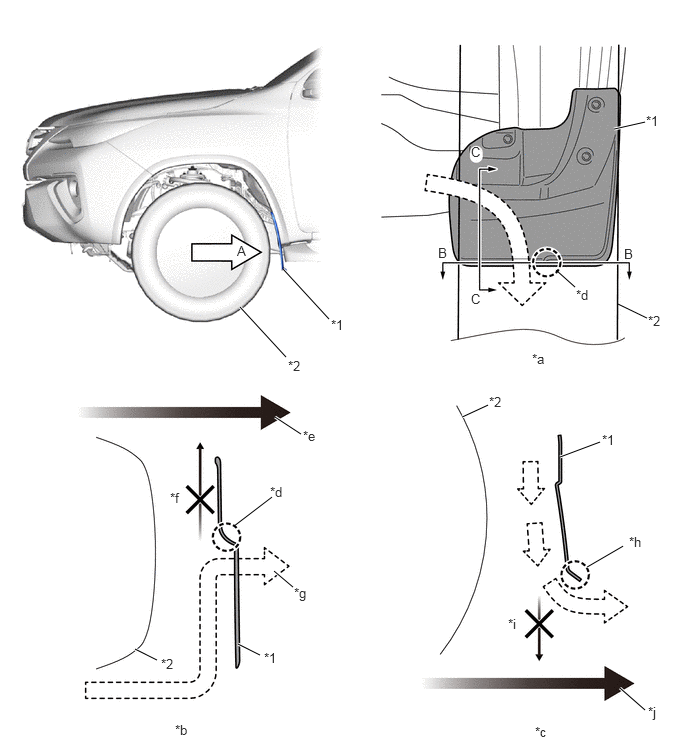
Aerodynamics of the front fender mudguard (*1 in illustration) is improved by adding wall and corner roundness of front fender mudguard to make airflow be sleek.
V113811C01
5.99,2.99 5.792,2.813 false 3.427,3.323 2.948,2.802 true 2.979,3.719 2.5,3.198 true 2.833,5.177 2.438,5.479 false 3.135,4.521 2.865,4.344 true 1.635,6.875 1.406,6.76 true 2.708,6.823 2.479,6.708 true 5.083,4.219 4.813,4.344 true 6.25,4.604 5.833,4.76 true 6.719,7.396 6.458,7.167 true 6.719,1.271 6.396,1.344 true 6.74,3.313 6.438,3.167 false 3.052,6.115 2.854,5.948 true 6.49,5.688 6.115,5.906 true 3.448,3.302 3.688,3.542 0.24,0.24 10 false *1 3,3.729 3.198,3.938 0.198,0.208 10 false *2 2.469,2.531 2.708,2.771 0.24,0.24 10 false A 4.563,2.552 4.719,2.75 0.156,0.198 10 false B 6.5,2.563 6.656,2.76 0.156,0.198 10 false B 6.729,1.177 6.969,1.417 0.24,0.24 10 false *1 6.75,3.26 6.99,3.5 0.24,0.24 10 false *2 4.906,3.031 5.073,3.24 0.167,0.208 10 false C 4.906,1.5 5.073,1.708 0.167,0.208 10 false C 6,2.99 6.24,3.229 0.24,0.24 10 false *d 3.156,4.458 3.354,4.667 0.198,0.208 10 false *e 2.813,5.042 3.01,5.25 0.198,0.208 10 false *d 3.063,6.094 3.26,6.302 0.198,0.208 10 false *g 2.75,6.771 2.948,6.979 0.198,0.208 10 false *1 1.771,5.104 1.969,5.313 0.198,0.208 10 false *f 1.677,6.833 1.875,7.042 0.198,0.208 10 false *2 1.823,7.521 2.021,7.729 0.198,0.208 10 false *b 5.573,7.542 5.771,7.75 0.198,0.208 10 false *c 5.094,4.104 5.292,4.313 0.198,0.208 10 false *2 6.271,4.5 6.469,4.708 0.198,0.208 10 false *1 6.552,5.563 6.75,5.771 0.198,0.208 10 false *h 5.292,6.417 5.49,6.625 0.198,0.208 10 false *i 6.75,7.333 6.948,7.542 0.198,0.208 10 false *j 5.542,3.656 5.781,3.896 0.24,0.24 10 false *a
*1 Front Fender Mudguard *2 Front Tire
*a View from A *b B - B Cross Section
*c C - C Cross Section *d Wall
*e Airflow from front side of the vehicle (Outside) *f Prevent from joining airflow for outside of vehicle
*g Make airflow be under front fender mudguard *h Added Corner Roundness
*i Prevent from joining airflow for beneath of the vehicle *j Airflow from beneath of the vehicle


·

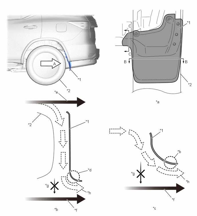
Aerodynamics of the rear body mudguard (quarter panel mudguard rear: *1 in illustration) is improved by adding corner roundness of rear body mudguard to make air flow be sleek.
V113812C01
6.469,1.073 6.802,0.854 true 6.563,2.688 6.833,2.99 false 2.156,2.885 2.427,3.188 false 2.552,2.51 2.823,2.813 true 2.125,3.396 2.448,3.677 true 2.531,4.688 3.104,4.448 true 1.49,4.135 1.167,4.458 false 2.958,6.896 3.146,7 false 6.583,6.385 6.719,6.531 false 5.969,6.885 6.229,7.188 true 5.521,5.031 5.833,4.802 true 6.344,5.74 6.479,5.573 false 2.865,6.292 3.188,6.208 false 2.427,7.26 2.688,7.563 true 6.729,2.167 6.875,2.385 0.146,0.219 10 false B 6.802,0.74 7.052,0.958 0.25,0.219 10 false *1 6.844,3 7.094,3.219 0.25,0.219 10 false *2 5.667,3.625 5.917,3.844 0.25,0.219 10 false *a 4.51,2.167 4.656,2.385 0.146,0.219 10 false B 4.677,1.885 4.823,2.104 0.146,0.219 10 false C 4.677,0.865 4.823,1.083 0.146,0.219 10 false C 1.938,2.24 2.083,2.458 0.146,0.219 10 false A 2.823,2.813 3.073,3.031 0.25,0.219 10 false *1 1.021,4.458 1.271,4.677 0.25,0.219 10 false *2 2.427,3.219 2.677,3.438 0.25,0.219 10 false *2 1.979,3.271 2.229,3.49 0.25,0.219 10 false *e 3.115,4.344 3.365,4.563 0.25,0.219 10 false *1 1.646,6.667 1.896,6.885 0.25,0.219 10 false *g 3.198,6.104 3.448,6.323 0.25,0.219 10 false *d 3.177,6.938 3.427,7.156 0.25,0.219 10 false *h 1.979,7.542 2.229,7.76 0.25,0.219 10 false *b 5.563,7.5 5.813,7.719 0.25,0.219 10 false *c 6.76,6.531 7.01,6.75 0.25,0.219 10 false *h 5.813,4.667 6.063,4.885 0.25,0.219 10 false *1 6.458,5.438 6.708,5.656 0.25,0.219 10 false *b 2.708,7.573 2.958,7.792 0.25,0.219 10 false *f 6.25,7.188 6.5,7.406 0.25,0.219 10 false *f 4.771,6.229 4.979,6.448 0.208,0.219 10 false *g
*1 Quarter Panel Mudguard Rear *2 Rear Tire
*a View from A *b B - B Cross Section
*c C - C Cross Section *d Added Corner Roundness
*e Airflow from rear side of the vehicle (Outside) *f Airflow from beneath of the vehicle
*g Prevent from joining airflow for beneath of the vehicle *h Make airflow be sleek


·

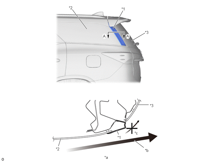
Improve aerodynamics by adding quarter pillar fin garnish (quarter window molding UPR: *1 in illustration) to make airflow sleek.
V113813C01
4.74,1.469 5.219,1.188 true 4.073,1.021 4.427,0.385 true 3.125,1.042 2.604,0.344 true 4.948,3.771 5.354,3.771 true 2.188,4.99 2.104,5.26 true 4.208,4.698 4.271,4.844 true 4.833,5.052 5.177,5.313 true 2.479,0.198 2.74,0.438 0.26,0.24 10 false *2 4.375,0.24 4.635,0.479 0.26,0.24 10 false *1 5.219,1.083 5.479,1.323 0.26,0.24 10 false *3 4.552,1.219 4.688,1.406 0.135,0.188 10 false A 2.01,5.281 2.271,5.521 0.26,0.24 10 false *2 4.844,4.708 5.104,4.948 0.26,0.24 10 false *c 5.396,3.719 5.656,3.958 0.26,0.24 10 false *3 4.229,4.865 4.49,5.104 0.26,0.24 10 false *1 3.76,5.583 3.948,5.771 0.188,0.188 10 false *a 5.219,5.333 5.479,5.573 0.26,0.24 10 false *b 3.708,1.219 3.844,1.406 0.135,0.188 10 false A
*1 Quarter Window Molding UPR *2 Quarter Window Assembly
*3 Back Window Glass - -
*a A - A Cross Section *b Airflow from front side of the vehicle
*c Make airflow be sleek - -


·

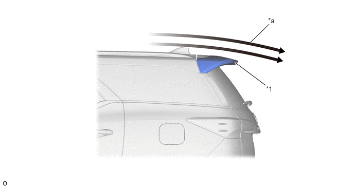
Reduction of aerodynamic drag by increasing the spoiler sub-assembly RR (*1 in illustration) length, resulting improved fuel efficiency.
V113814C01
5.063,0.865 5.448,0.49 true 4.75,1.26 5.375,1.729 true 5.385,1.719 5.573,1.927 0.188,0.208 10 false *1 5.427,0.333 5.615,0.542 0.188,0.208 10 false *a
*1 Spoiler Sub-assembly RR - -
*a Smoother Airflow - -