Home › Engine / Hybrid System › 1GR-FE ENGINE CONTROL › SFI SYSTEM
RM33K0E _51 Engine / Hybrid System _043565 1GR-FE ENGINE CONTROL _0222009 SFI SYSTEM J

1GR-FE ENGINE CONTROL  SFI SYSTEM  ECM Power Source Circuit  


DESCRIPTION

When the engine switch is turned on (IG), battery voltage is applied to the IGSW terminal of the ECM. The output signal from the MREL terminal of the ECM causes current to flow to the coil of the EFI-MAIN NO.1 relay, closing the contact of the EFI-MAIN NO.1 relay and supplying power to terminals +B and +B2 of the ECM.

WIRING DIAGRAM
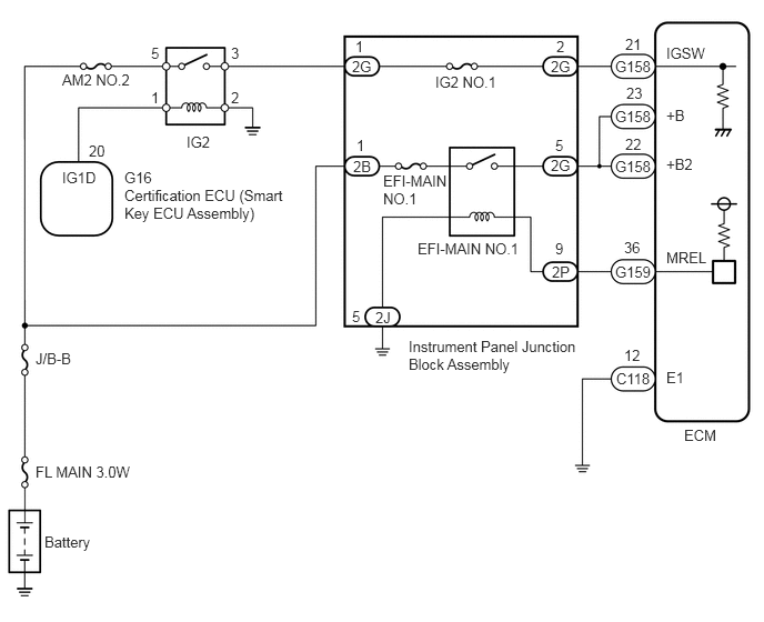
A375081E01
0.583,0.667 1.333,0.833 0.75,0.167 10 false AM2 NO.2 1.417,0.417 1.583,0.583 0.167,0.167 10 false 5 2.167,0.833 2.333,1 0.167,0.167 10 false 2 1.417,0.833 1.583,1 0.167,0.167 10 false 1 2.167,0.417 2.333,0.583 0.167,0.167 10 false 3 0.833,1.333 1.083,1.5 0.25,0.167 10 false 20 0.583,1.583 1,1.75 0.417,0.167 10 false IG1D 1.167,1.583 1.5,1.75 0.333,0.167 10 false G16 1.167,1.75 2.75,2.167 1.583,0.417 10 false Certification ECU (Smart Key ECU Assembly) 0.333,3.281 0.75,3.448 0.417,0.167 10 false J/B-B 0.333,4.344 1.333,4.51 1,0.167 10 false FL MAIN 3.0W 0.417,5 0.917,5.25 0.5,0.25 10 false Battery 3.333,0.354 3.5,0.521 0.167,0.167 10 false 1 3.302,0.542 3.552,0.708 0.25,0.167 10 false 2G 3.344,1.281 3.51,1.448 0.167,0.167 10 false 1 3.313,1.479 3.563,1.646 0.25,0.167 10 false 2B 3.521,2.896 3.771,3.063 0.25,0.167 10 false 2J 3.302,2.885 3.469,3.052 0.167,0.167 10 false 5 3.833,3.167 5.5,3.583 1.667,0.417 10 false Instrument Panel Junction Block Assembly 3.917,2.25 4.917,2.417 1,0.167 10 false EFI-MAIN NO.1 4.083,0.688 4.75,0.854 0.667,0.167 10 false IG2 NO.1 5.219,0.354 5.385,0.521 0.167,0.167 10 false 2 5.167,0.542 5.417,0.708 0.25,0.167 10 false 2G 5.208,1.281 5.375,1.448 0.167,0.167 10 false 5 5.167,1.469 5.417,1.635 0.25,0.167 10 false 2G 5.208,2.25 5.375,2.417 0.167,0.167 10 false 9 5.177,2.469 5.427,2.635 0.25,0.167 10 false 2P 5.865,0.333 6.115,0.5 0.25,0.167 10 false 21 5.771,0.542 6.188,0.708 0.417,0.167 10 false G158 5.875,0.792 6.125,0.958 0.25,0.167 10 false 23 5.865,1.271 6.115,1.438 0.25,0.167 10 false 22 5.854,2.24 6.104,2.406 0.25,0.167 10 false 36 5.771,2.469 6.188,2.635 0.417,0.167 10 false G159 5.854,3.25 6.104,3.417 0.25,0.167 10 false 12 5.781,3.469 6.198,3.635 0.417,0.167 10 false C118 6.25,3.458 6.5,3.625 0.25,0.167 10 false E1 6.25,2.333 6.667,2.5 0.417,0.167 10 false MREL 6.25,1.458 6.583,1.625 0.333,0.167 10 false +B2 6.25,1 6.583,1.167 0.333,0.167 10 false +B 6.25,0.417 6.667,0.583 0.417,0.167 10 false IGSW 6.417,4 6.833,4.167 0.417,0.167 10 false ECM 1.75,1.25 2.083,1.417 0.333,0.167 10 false IG2 5.771,1.01 6.188,1.177 0.417,0.167 10 false G158 5.771,1.479 6.188,1.646 0.417,0.167 10 false G158 3.594,1.615 4.26,1.948 0.667,0.333 10 false EFI-MAIN NO.1

CAUTION / NOTICE / HINT

NOTICE:
·

Inspect the fuses for circuits related to this system before performing the following procedure.

·

After turning engine switch off, waiting time may be required before disconnecting the cable from the negative (-) battery terminal. Therefore, make sure to read the disconnecting the cable from the negative (-) battery terminal notices before proceeding with work.

Click hereGeneral>INTRODUCTION>REPAIR INSTRUCTION>PRECAUTION


PROCEDURE
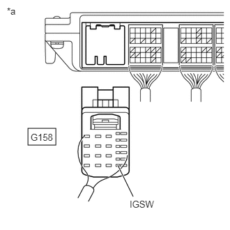
1.CHECK TERMINAL VOLTAGE (IGSW VOLTAGE)
A353955C03
0.417,1.917 0.833,2.167 0.417,0.25 1.99,2.938 1.76,2.469 true 0.104,0.083 0.417,0.24 0.313,0.156 10 false *a 1.938,2.969 2.552,3.167 0.615,0.198 10 false IGSW 0.458,1.969 0.917,2.167 0.458,0.198 10 false G158
*a Rear view of wire harness connector (to ECM)


a.

Disconnect the ECM connector.


b.

Turn the engine switch on (IG).


c.

Measure the voltage according to the value(s) in the table below.

Standard Voltage:
Tester Connection Condition Specified Condition
G158-21 (IGSW) - Body ground Engine switch on (IG) 11 to 14 V


Result:
Proceed to
OK
NG


OK

2.CHECK HARNESS AND CONNECTOR (ECM - BODY GROUND)

NG

6.CHECK HARNESS AND CONNECTOR (NO. 4 INSTRUMENT PANEL RELAY BLOCK - ECM)
2.CHECK HARNESS AND CONNECTOR (ECM - BODY GROUND)
a.

Disconnect the ECM connector.


b.

Measure the resistance according to the value(s) in the table below.

Standard Resistance:
Tester Connection Condition Specified Condition
C118-12 (E1) - Body ground Always Below 1 Ω


Result:
Proceed to
OK
NG


OK

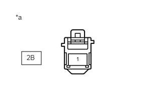
3.CHECK TERMINAL VOLTAGE (POWER SOURCE OF INSTRUMENT PANEL JUNCTION BLOCK ASSEMBLY)

NG

REPAIR OR REPLACE HARNESS OR CONNECTOR

3.CHECK TERMINAL VOLTAGE (POWER SOURCE OF INSTRUMENT PANEL JUNCTION BLOCK ASSEMBLY)
a.
A201293C08
0.448,1.063 0.854,1.333 0.406,0.271 0.552,1.104 0.865,1.302 0.313,0.198 10 false 2B 0.323,0.271 0.635,0.469 0.313,0.198 10 false *a
*a Front view of wire harness connector
(to Instrument Panel Junction Block Assembly)


Disconnect the instrument panel junction block assembly connector.


b.

Measure the voltage according to the value(s) in the table below.

Standard Voltage:
Tester Connection Condition Specified Condition
2B-1 - Body ground Always 11 to 14 V


Result:
Proceed to
OK
NG


OK

4.INSPECT EFI-MAIN NO. 1 RELAY

NG

REPAIR OR REPLACE HARNESS OR CONNECTOR (BATTERY - INSTRUMENT PANEL JUNCTION BLOCK ASSEMBLY)

4.INSPECT EFI-MAIN NO. 1 RELAY
a.

Result:
Proceed to
OK
NG


OK

5.CHECK HARNESS AND CONNECTOR (INSTRUMENT PANEL JUNCTION BLOCK ASSEMBLY - ECM, BODY GROUND)

NG

REPLACE INSTRUMENT PANEL JUNCTION BLOCK ASSEMBLY

5.CHECK HARNESS AND CONNECTOR (INSTRUMENT PANEL JUNCTION BLOCK ASSEMBLY - ECM, BODY GROUND)
a.

Disconnect the instrument panel junction block assembly connector.


b.

Disconnect the ECM connector.


c.

Measure the resistance according to the value(s) in the table below.

Standard Resistance:
Tester Connection Condition Specified Condition
2G-5 - G158-23 (+B) Always Below 1 Ω
2G-5 - G158-22 (+B2) Always Below 1 Ω
2P-9 - G159-36 (MREL) Always Below 1 Ω
2J-5 - Body ground Always Below 1 Ω
2G-5 or G158-23 (+B) - Body ground and other terminals Always 10 kΩ or higher
2G-5 or G158-22 (+B2) - Body ground and other terminals Always 10 kΩ or higher
2P-9 or G159-36 (MREL) - Body ground and other terminals Always 10 kΩ or higher


Result:
Proceed to
OK
NG


OK

PROCEED TO NEXT SUSPECTED AREA SHOWN IN PROBLEM SYMPTOMS TABLE

NG

REPAIR OR REPLACE HARNESS OR CONNECTOR

6.CHECK HARNESS AND CONNECTOR (NO. 4 INSTRUMENT PANEL RELAY BLOCK - ECM)
a.

Disconnect the ECM connector.


b.

Remove the IG2 relay from No. 4 instrument panel relay block.


c.

Measure the resistance according to the value(s) in the table below.

Standard Resistance:
Tester Connection Condition Specified Condition
G158-21 (IGSW) - IG2 Relay terminal 3 Always Below 1 Ω
G158-21 (IGSW) or IG2 Relay terminal 3 - Body ground and other terminals Always 10 kΩ or higher


Result:
Proceed to
OK
NG


OK

7.CHECK HARNESS AND CONNECTOR (BATTERY - NO. 4 INSTRUMENT PANEL RELAY BLOCK)

NG

REPAIR OR REPLACE HARNESS OR CONNECTOR

7.CHECK HARNESS AND CONNECTOR (BATTERY - NO. 4 INSTRUMENT PANEL RELAY BLOCK)
a.

Disconnect the cable from the positive (+) battery terminal.


b.

Remove the IG2 relay from No. 4 instrument panel relay block.


c.

Measure the resistance according to the value(s) in the table below.

Standard Resistance:
Tester Connection Condition Specified Condition
Battery cable positive (+) terminal - IG2 Relay terminal 5 Always Below 1 Ω
Battery cable positive (+) terminal or IG2 Relay terminal 5 - Body ground and other terminals Always 10 kΩ or higher


Result:
Proceed to
OK
NG


OK

NG

REPAIR OR REPLACE HARNESS OR CONNECTOR