STEERING GEAR / LINKAGE STEERING GEAR REASSEMBLY
CAUTION / NOTICE / HINT
- NOTICE:
- ·
When using a vise, place aluminum plates between the part and vise.
·When using a vise, do not overtighten it.
- HINT:
- ·
Use the same procedure for RHD and LHD vehicles.
·The procedure listed below is for LHD vehicles.
PROCEDURE

 1.INSTALL STEERING RACK BOOT LH
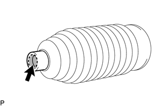

|
Lithium Soap Base Glycol Grease |

|
Apply Grease Area |
Apply lithium soap base glycol grease to the steering rack boot LH shown in the illustration.
Install the steering rack boot LH.
- NOTICE:
- ·
Make sure that the steering rack boot LH is free of rust and foreign matter.
·Be careful not to damage or twist the steering rack boot.
2.INSTALL STEERING RACK BOOT RH
- HINT:
-
Use the same procedure described for the LH side.
3.INSTALL STEERING RACK BOOT CLAMP LH
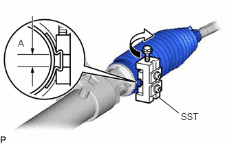
Using SST, install a new steering rack boot clamp LH as shown in the illustration.
- SST
- 09240-00020
09521-24010
- Standard clearance (A):
3.0 mm (0.118 in.) or less
- NOTICE:
-
Be careful not to damage the steering rack boot.
4.INSTALL STEERING RACK BOOT CLAMP RH
- HINT:
-
Use the same procedure described for the LH side.
5.INSTALL STEERING RACK BOOT CLIP LH
Using pliers, install the steering rack boot clip LH.
6.INSTALL STEERING RACK BOOT CLIP RH
- HINT:
-
Use the same procedure described for the LH side.
7.INSPECT POWER STEERING LINK ASSEMBLY
8.INSTALL STEERING TURN PRESSURE TUBE
Apply power steering fluid to 3 new O-rings, and install the O-rings to the steering turn pressure tubes.
for LHD:
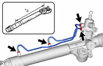
Using a union nut wrench, install the 2 steering turn pressure tubes.
- Torque:
- 12.5 N*m (127 kgf*cm, 9 ft.*lbf)
- NOTICE:
-
Do not damage the O-rings.
- HINT:
- ·
Calculate the torque wrench reading when changing the fulcrum length of the torque wrench.
Click hereGeneral>INTRODUCTION>REPAIR INSTRUCTION>PRECAUTION
·When using a union nut wrench (fulcrum length of 20 mm (0.7874 in.)) + torque wrench (fulcrum length of 162 mm (6.3779 in.)): 11.1 N*m (113 kgf*cm, 8 ft.*lbf)
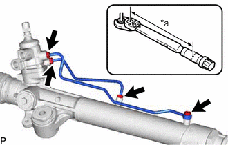
| *a | Torque Wrench Fulcrum Length |
for RHD:
Using a union nut wrench, install the 2 steering turn pressure tubes.
- Torque:
- 12.5 N*m (127 kgf*cm, 9 ft.*lbf)
- NOTICE:
-
Do not damage the O-rings.
- HINT:
- ·
Calculate the torque wrench reading when changing the fulcrum length of the torque wrench.
Click hereGeneral>INTRODUCTION>REPAIR INSTRUCTION>PRECAUTION
·When using a union nut wrench (fulcrum length of 20 mm (0.7874 in.)) + torque wrench (fulcrum length of 162 mm (6.3779 in.)): 11.1 N*m (113 kgf*cm, 8 ft.*lbf)
Install the 2 new gaskets and union bolt.
- Torque:
- 29.4 N*m (300 kgf*cm, 22 ft.*lbf)
45047
9.INSTALL TIE ROD END SUB-ASSEMBLY LH
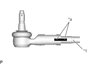
| *1 | Rack End |
| *a | Matchmark |
Screw the lock nut and tie rod end sub-assembly LH onto the rack end until the matchmarks are aligned.
After adjusting the toe-in, tighten the lock nut.
45046
10.INSTALL TIE ROD END SUB-ASSEMBLY RH
- HINT:
-
Use the same procedure described for the LH side.