INTERIOR PANELS / TRIM UPPER INSTRUMENT PANEL REASSEMBLY
CAUTION / NOTICE / HINT
- HINT:
- ·
Use the same procedure for RHD and LHD vehicles.
·The procedure listed below is for LHD vehicles.
PROCEDURE

 55557A
1.INSTALL GLOVE COMPARTMENT DOOR CHECK CUSHION
- HINT:
-
Use the same procedure for both glove compartment door check cushions.
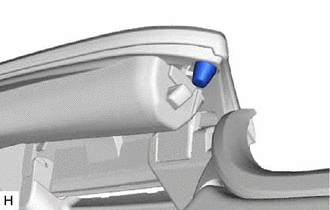
Install the glove compartment door check cushion.
55474B
2.INSTALL INSTRUMENT CLUSTER FINISH PANEL GARNISH
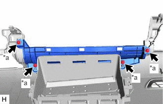
| *a | Screw <C> |
Install the instrument cluster finish panel garnish with the 4 screws <C>.
73960A
3.INSTALL INSTRUMENT PANEL PASSENGER WITHOUT DOOR AIRBAG ASSEMBLY
82142
4.INSTALL NO. 2 INSTRUMENT PANEL WIRE
Connect the airbag connector to the instrument panel passenger without door airbag assembly.
- NOTICE:
-
When connecting any airbag connector, take care not to damage the airbag wire harness.
Push in the connector lock to install the airbag connector.
Connect the connector and attach the clamp to install the No. 2 instrument panel wire.
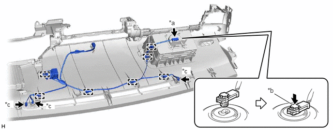
| *a | Airbag Connector | *b | Connector Lock |
| *c | Connector | - | - |
55368C
5.INSTALL METER MOUNTING BRACKET
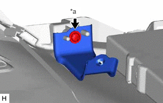
| *a | Screw <C> |
for LH Side:
Install the meter mounting bracket with the screw <C>.
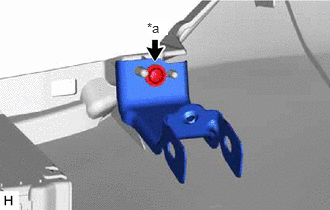
| *a | Screw <C> |
for RH Side:
Install the meter mounting bracket with the screw <C>.
55359C
6.INSTALL NO. 5 INSTRUMENT PANEL CUSHION
- NOTICE:
-
Installing the part with double-sided tape residue still remaining can cause poor adhesion. Therefore, using a cloth or other material, clean the part until the residue is completely removed (when reusing the upper instrument panel sub-assembly).
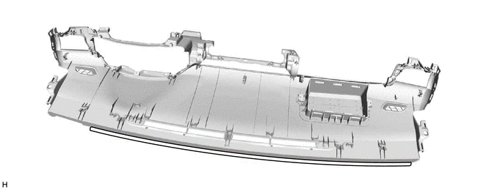
Remove the peeling paper from a new No. 5 instrument panel cushion and press firmly to install the No. 5 instrument panel cushion in the position shown in the illustration.
55355
7.INSTALL NO. 1 INSTRUMENT PANEL CUSHION
- NOTICE:
-
Installing the part with double-sided tape residue still remaining can cause poor adhesion. Therefore, using a cloth or other material, clean the part until the residue is completely removed (when reusing the upper instrument panel sub-assembly).
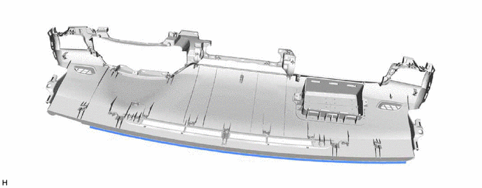
Remove the peeling paper from a new No. 1 instrument panel cushion and press firmly to install the No. 1 instrument panel cushion in the position shown in the illustration.
55357B
8.INSTALL NO. 3 INSTRUMENT PANEL CUSHION
- NOTICE:
-
Installing the part with double-sided tape residue still remaining can cause poor adhesion. Therefore, using a cloth or other material, clean the part until the residue is completely removed (when reusing the upper instrument panel sub-assembly).
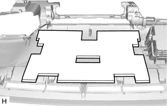
Remove the peeling paper from a new No. 3 instrument panel cushion and press firmly to install the No. 3 instrument panel cushion in the position shown in the illustration.
55356C
9.INSTALL NO. 2 INSTRUMENT PANEL CUSHION
- NOTICE:
-
Installing the part with double-sided tape residue still remaining can cause poor adhesion. Therefore, using a cloth or other material, clean the part until the residue is completely removed (when reusing the upper instrument panel sub-assembly).
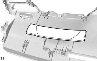
for Driver Side:
Remove the peeling paper from a new No. 2 instrument panel cushion and press firmly to install the No. 2 instrument panel cushion in the position shown in the illustration.
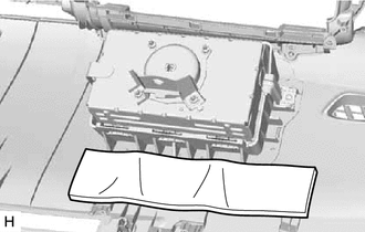
for Passenger Side:
Remove the peeling paper from a new No. 2 instrument panel cushion and press firmly to install the No. 2 instrument panel cushion in the position shown in the illustration.
55660
10.INSTALL NO. 2 INSTRUMENT PANEL REGISTER ASSEMBLY
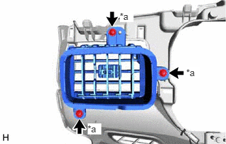
| *a | Screw <C> |
Install the No. 2 instrument panel register assembly with the 3 screws <C>.
55650
11.INSTALL NO. 1 INSTRUMENT PANEL REGISTER ASSEMBLY
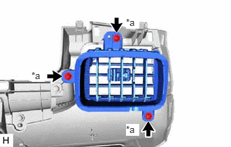
| *a | Screw <C> |
Install the No. 1 instrument panel register assembly with the 3 screws <C>.
55670A
12.INSTALL CENTER INSTRUMENT PANEL REGISTER ASSEMBLY
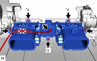
| *a | Screw <C> |
| *b | Connector |
Install the center instrument panel register assembly with the 5 screws <C>.
Connect the connector and attach the clamp.
86860
13.INSTALL NAVIGATION ANTENNA ASSEMBLY (w/ Navigation System)
55844
14.INSTALL NO. 2 HEATER TO REGISTER DUCT
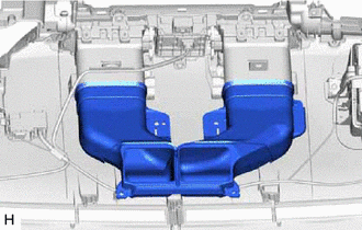
w/o Navigation System:
Install the No. 2 heater to register duct.
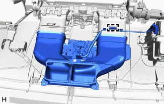
w/ Navigation System:
Install the No. 2 heater to register duct.
Attach the clamp.
55084E
15.INSTALL NO. 1 HEATER TO REGISTER DUCT SUB-ASSEMBLY
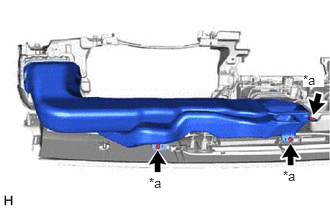
| *a | Screw <C> |
Install the No. 1 heater to register duct sub-assembly with the 3 screws <C>.
55085
16.INSTALL NO. 2 HEATER TO REGISTER DUCT SUB-ASSEMBLY
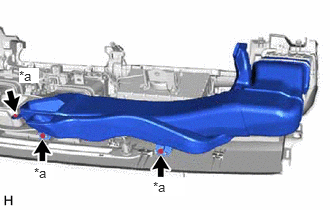
| *a | Screw <C> |
Install the No. 2 heater to register duct sub-assembly with the 3 screws <C>.
55950G
17.INSTALL DEFROSTER NOZZLE ASSEMBLY
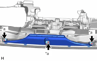
| *a | Screw <C> |
Install the defroster nozzle assembly with the 3 screws <C>.