VF2CM TRANSFER / 4WD / AWD TRANSFER ASSEMBLY REASSEMBLY
PROCEDURE

 36239
1.INSTALL TRANSFER DRIVE CLUTCH HUB
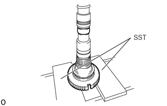
Using SST and a press, install a new transfer drive clutch hub.
- SST
- 09527-10011
- NOTICE:
- ·
When replacing the transfer drive clutch hub, replace it with a new one and align it with the rear transfer output shaft.
·Make sure the transfer drive clutch hub contacts the edge of the rear transfer output shaft, but do not press it in more than necessary.
36236
2.INSTALL FRONT DRIVE CLUTCH SLEEVE
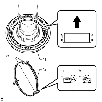
| *1 | Front Drive Clutch Sleeve |
| *2 | Transfer Synchromesh Shifting Key Spring |
| *3 | No. 1 Synchromesh Shifting Key |
| *a | CORRECT |
| *b | INCORRECT |

|
Rear Side |
Install the front drive clutch sleeve.
- NOTICE:
-
Install the front drive clutch sleeve in the correct direction.
Install the 2 transfer synchromesh shifting key springs and 3 No. 1 synchromesh shifting keys.
- NOTICE:
- ·
Install the shifting key springs so that their openings do not overlap as shown in the illustration.
·Install the No. 1 synchromesh shifting keys so that they are securely attached to the 2 transfer synchromesh shifting key springs.
·Install the No. 1 synchromesh shifting keys so that they do not rest on the ends of the transfer synchromesh shifting key springs as shown in the illustration.
·Make sure that the transfer synchromesh shifting key springs are firmly connected to the No. 1 synchromesh shifting key.
·Make sure that the front drive clutch sleeve moves smoothly.
36209
3.INSTALL TRANSFER SYNCHRONIZER RING SET
- NOTICE:
-
Be careful not to drop the front drive clutch sleeve and No. 1 synchromesh shifting key.
Apply transfer oil to the transfer synchronizer ring set.
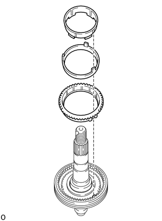
Install the transfer synchronizer ring set.
- NOTICE:
-
Align the key groove of the transfer synchronizer ring set with the No. 1 synchromesh shifting key, and then install the transfer synchronizer ring set.
36205
4.INSTALL TRANSFER DRIVE SPROCKET SUB-ASSEMBLY
- NOTICE:
-
Be careful not to drop the front drive clutch sleeve and No. 1 synchromesh shifting key.
Apply transfer oil to the rolling and thrusting surfaces of the needle roller bearing, and the fitting surfaces of the transfer drive sprocket sub-assembly and front drive clutch sleeve.
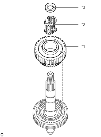
| *1 | Transfer Drive Sprocket Sub-assembly |
| *2 | Needle Roller Bearing |
| *3 | No. 1 Transfer Output Shaft Spacer |
Install the transfer drive sprocket sub-assembly.
Install the needle roller bearing.
Install the No. 1 transfer output shaft spacer.
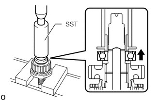
|
|
Rear Side |
Apply transfer oil to a new rear transfer output shaft radial ball bearing and the press-fit portion of the rear transfer output shaft.
Using SST and a press, install the rear transfer output shaft radial ball bearing.
- SST
- 09316-60011 (09316-00011, 09316-00051)
- NOTICE:
- ·
Install the rear transfer output shaft radial ball bearing with the installation groove of the transfer output shaft snap ring facing the rear side as shown in the illustration.
·Make sure the rear transfer output shaft radial ball bearing contacts the edge of the No. 1 transfer output shaft spacer, but do not press it in more than necessary.
·Make sure that the transfer drive sprocket sub-assembly moves smoothly.
Measure the transfer drive sprocket sub-assembly thrust clearance.
Click hereDrivetrain>VF2CM TRANSFER / 4WD / AWD>TRANSFER ASSEMBLY>INSPECTION
36237
5.INSTALL TRANSFER CLUTCH HUB
- NOTICE:
-
Be careful not to drop the front drive clutch sleeve and No. 1 synchromesh shifting key.
Apply transfer oil to the transfer clutch hub and the press-fit portion of the rear transfer output shaft.
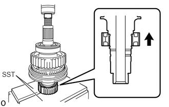
|
|
Rear Side |
Using SST and a press, install the transfer clutch hub.
- SST
- 09527-10011
- NOTICE:
- ·
Install the transfer clutch hub in the correct direction.
·Make sure the transfer clutch hub contacts the edge of the rear transfer output shaft, but do not press it in more than necessary.
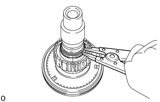
Select a transfer clutch hub shaft snap ring from the table below so that the clearance between the transfer clutch hub and transfer clutch hub shaft snap ring is 0.15 mm (0.00590 in.) or less.
- Snap Ring Thickness:
Part No. Specified Condition 90520-39013 2.00 to 2.05 mm (0.0788 to 0.0807 in.) 90520-T0200 90520-39014 2.05 to 2.10 mm (0.0808 to 0.0826 in.) 90520-T0201 90520-39004 2.10 to 2.15 mm (0.0827 to 0.0846 in.) 90520-T0191 90520-39005 2.15 to 2.20 mm (0.0847 to 0.0866 in.) 90520-T0192 90520-39006 2.20 to 2.25 mm (0.0867 to 0.0885 in.) 90520-T0193 90520-39007 2.25 to 2.30 mm (0.0886 to 0.0905 in.) 90520-T0194 90520-39008 2.30 to 2.35 mm (0.0906 to 0.0925 in.) 90520-T0195 90520-39009 2.35 to 2.40 mm (0.0926 to 0.0944 in.) 90520-T0196 90520-39010 2.40 to 2.45 mm (0.0945 to 0.0964 in.) 90520-T0197 90520-39011 2.45 to 2.50 mm (0.0965 to 0.0984 in.) 90520-T0198 90520-39012 2.50 to 2.55 mm (0.0985 to 0.1003 in.) 90520-T0199
Using a snap ring expander, install a new transfer clutch hub shaft snap ring.
Install the transfer high and low clutch sleeve.
- NOTICE:
-
Make sure that the transfer high and low clutch sleeve moves smoothly.
36292A
6.INSTALL TRANSFER DRIVEN SPROCKET BEARING
Apply transfer oil to 2 new transfer driven sprocket bearings and the press-fit portion of the transfer driven sprocket.
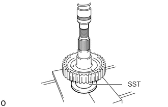
for Rear Side:
Using SST and a press, install the transfer driven sprocket bearing.
- SST
- 09316-60011 (09316-00031)
- NOTICE:
- ·
Make sure the transfer driven sprocket bearing contacts the edge of the transfer driven sprocket, but do not press it in more than necessary.
·Make sure that the transfer driven sprocket bearing moves smoothly.
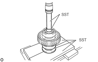
for Front Side:
Using SST and a press, install the transfer driven sprocket bearing.
- SST
- 09950-60010 (09951-00290)
09950-70010 (09951-07100)
09316-60011 (09316-00031)
09527-10011
- NOTICE:
- ·
Make sure the transfer driven sprocket bearing contacts the edge of the transfer driven sprocket, but do not press it in more than necessary.
·Make sure that the transfer driven sprocket bearing moves smoothly.
36410J
7.INSTALL TRANSFER SHIFT ACTUATOR ASSEMBLY
Apply transfer oil to the O-ring of the transfer shift actuator assembly.
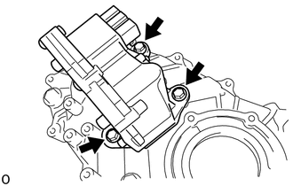
Install the transfer shift actuator assembly with the 3 bolts.
- Torque:
- 20 N*m (204 kgf*cm, 15 ft.*lbf)
- NOTICE:
-
Do not damage the O-ring.
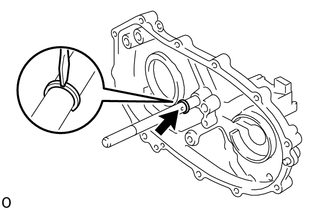
Using a screwdriver and hammer, install the transfer gear shift fork shaft snap ring.
- HINT:
-
Install only the transfer gear shift fork shaft snap ring on the rear side of the transfer shift actuator shaft.
36231
8.INSTALL REAR TRANSFER OUTPUT SHAFT, TRANSFER FRONT DRIVE CHAIN, TRANSFER DRIVEN SPROCKET
- NOTICE:
- ·
Be careful not to drop the front drive clutch sleeve and No. 1 synchromesh shifting key.
·When using a vise, place aluminum plates between the part and vise.
·When using a vise, do not overtighten it.
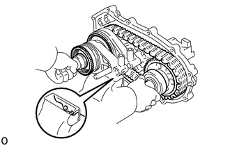
Install the rear transfer output shaft, transfer driven sprocket and transfer front drive chain with the No. 1 transfer gear shift fork and No. 2 transfer gear shift fork.
- HINT:
-
When installation under normal temperatures is difficult, heat the rear transfer case to approximately 50 to 80 °C (122 to 176 °F), and then install it.
- CAUTION:
-
Be careful not to burn yourself when the rear transfer case temperature is high.
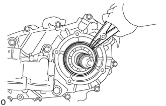
Using a snap ring expander, install the transfer output shaft shaft snap ring.
- NOTICE:
-
After installation, if there is any clearance along the inside diameter of the transfer output shaft snap ring, replace it with a new one.
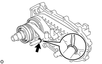
Using a screwdriver and hammer, install the transfer gear shift fork shaft snap ring.
36313F
9.INSTALL TRANSFER FRONT DRIVE SHIFT FORK SHAFT
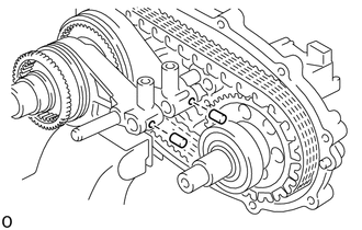
Using a magnet hand, install the 2 shift interlock pin or rollers.
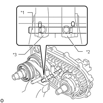
| *1 | Transfer Front Drive Shift Fork Shaft |
| *2 | No. 1 Transfer Gear Shift Fork |
| *3 | No. 2 Transfer Gear shift fork |
To install the transfer front drive shift fork shaft, shift the No. 1 transfer gear shift fork and No. 2 transfer gear shift fork to the positions shown in the illustration.
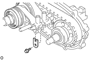
Install the transfer shift shaft stopper with the bolt.
- Torque:
- 19 N*m (194 kgf*cm, 14 ft.*lbf)
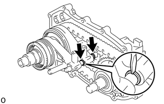
Using a screwdriver and hammer, install the 2 transfer gear shift fork shaft snap rings.
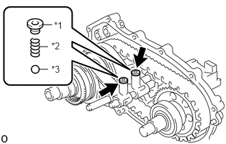
| *1 | Shift Detent Ball Spring Plug |
| *2 | Shift Detent Ball Compression Spring |
| *3 | Shift Detent Ball |
Clean the 2 shift detent ball spring plug holes.
Install the 2 shift detent balls and 2 shift detent ball compression springs.
Using a 6 mm hexagon wrench, install 2 new shift detent ball spring plugs.
- Torque:
- 18.6 N*m (190 kgf*cm, 14 ft.*lbf)
36270A
10.INSTALL TRANSFER LOW PLANETARY GEAR BEARING
Apply transfer oil to a new transfer low planetary gear bearing.
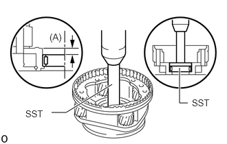
Using SST and a press, install the transfer low planetary gear bearing as shown in the illustration.
- SST
- 09950-60010 (09951-00470, 09951-00570, 09952-06010)
09950-70010 (09951-07150)
- Drive in depth (A):
7.7 to 8.3 mm (0.3032 to 0.3267 in.)
36210A
11.INSTALL TRANSFER INPUT SHAFT BEARING
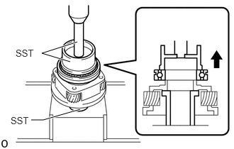
|
|
Front Side |
Using SST and a press, install a new transfer input shaft bearing.
- SST
- 09223-15020
09515-30010
09950-70010 (09951-07100)
- NOTICE:
- ·
Install the transfer input shaft bearing with the installation groove of the transfer low planetary gear bearing shaft snap ring facing the front side as shown in the illustration.
·Make sure the transfer input shaft bearing contacts the edge of the transfer low planetary ring gear, but do not press it in more than necessary.
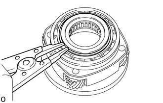
Select a transfer input bearing shaft snap ring from the table below so that the clearance between the transfer input shaft bearing and transfer input bearing shaft snap ring is 0.1 mm (0.00393 in.) or less.
- Snap Ring Thickness:
Part No. Mark Specified Condition 90520-72001 1 1.45 to 1.50 mm (0.0571 to 0.0590 in.) 90520-T0136 90520-72002 2 1.50 to 1.55 mm (0.0591 to 0.0610 in.) 90520-T0137 90520-72003 3 1.55 to 1.60 mm (0.0611 to 0.0629 in.) 90520-T0138 90520-72004 4 1.60 to 1.65 mm (0.0630 to 0.0649 in.) 90520-T0139 90520-72005 5 1.65 to 1.70 mm (0.0650 to 0.0669 in.) 90520-T0140
Using a snap ring expander, install a new transfer input bearing shaft snap ring.
36216A
12.INSTALL NO. 1 TRANSFER INPUT SHAFT SEAL RING
Apply transfer oil to the 2 No. 1 transfer input shaft seal rings.
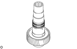
Install the 2 No. 1 transfer input shaft seal rings.
- NOTICE:
-
When installing the No. 1 transfer input shaft seal ring, do not expand the inside diameter to 65.0 mm (2.55 in.) or more.
36211
13.INSTALL TRANSFER INPUT SHAFT
Apply transfer oil to the transfer low planetary gear bearing.
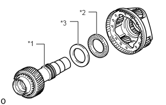
| *1 | Transfer Input Shaft |
| *2 | Transfer Low Planetary Gear Bearing |
| *3 | No. 1 Transfer Thrust Bearing Race |
Install the transfer low planetary gear bearing, No. 1 transfer thrust bearing race and transfer input shaft.
- NOTICE:
-
When selecting a transfer low planetary gear bearing and No. 1 transfer thrust bearing race, select and install parts from the same manufacturer.
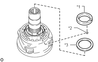
| *1 | Transfer Input Gear Stopper |
| *2 | Transfer Input Gear Stopper Ball |
| *3 | Manual Transfer Planetary Carrier Washer |
Apply transfer oil to the manual transfer planetary carrier washer.
Install the manual transfer planetary carrier washer.
Install the transfer input gear stopper and transfer input gear stopper ball.
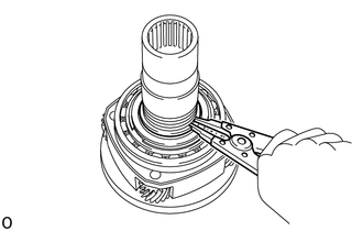
Select a transfer input bearing shaft snap ring from the table below so that the thrust clearance of the transfer input gear stopper shaft snap ring is 0.05 to 0.15 mm (0.00197 to 0.00590 in.).
- Snap Ring Thickness:
Part No. Specified Condition 90520-44003 2.10 to 2.15 mm (0.0827 to 0.0846 in.) 90520-T0202 90520-44004 2.15 to 2.20 mm (0.0847 to 0.0866 in.) 90520-T0203 90520-44005 2.20 to 2.25 mm (0.0867 to 0.0885 in.) 90520-T0204 90520-44006 2.25 to 2.30 mm (0.0886 to 0.0905 in.) 90520-T0205 90520-44007 2.30 to 2.35 mm (0.0906 to 0.0925 in.) 90520-T0206 90520-44008 2.35 to 2.40 mm (0.0926 to 0.0944 in.) 90520-T0207 90520-44009 2.40 to 2.45 mm (0.0945 to 0.0964 in.) 90520-T0208 90520-44010 2.45 to 2.50 mm (0.0965 to 0.0984 in.) 90520-T0209 90520-44011 2.50 to 2.55 mm (0.0985 to 0.100 in.) 90520-T0210 90520-44012 2.55 to 2.60 mm (0.101 to 0.102 in.) 90520-T0211 90520-44013 2.60 to 2.65 mm (0.103 to 0.104 in.) 90520-T0212 90520-44014 2.65 to 2.70 mm (0.105 to 0.106 in.) 90520-T0213 90520-44015 2.70 to 2.75 mm (0.107 to 0.108 in.) 90520-T0214 90520-44016 2.75 to 2.80 mm (0.109 to 0.110 in.) 90520-T0215 90520-44017 2.80 to 2.85 mm (0.111 to 0.112 in.) 90520-T0216 90520-44018 2.85 to 2.90 mm (0.113 to 0.114 in.) 90520-T0217 90520-44019 2.90 to 2.95 mm (0.115 to 0.116 in.) 90520-T0218 90520-44020 2.95 to 3.00 mm (0.117 to 0.118 in.) 90520-T0219 90520-44021 3.00 to 3.05 mm (0.119 to 0.120 in.) 90520-T0220
Using a snap ring expander, install a new transfer input gear stopper shaft snap ring.
- NOTICE:
-
After installation, if there is any clearance along the inside diameter of the transfer input gear stopper shaft snap ring, replace it with a new one.
36284
14.INSTALL TRANSFER LOW PLANETARY GEAR SPLINE PIECE
Apply transfer oil to the transfer output shaft front needle roller bearing.
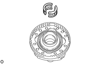
Install the transfer output shaft front needle roller bearing.
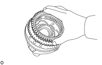
Install the transfer low planetary gear spline piece.
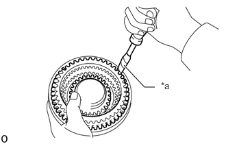
| *a | Protective Tape |
Using a screwdriver, install the transfer low planetary gear shaft snap ring.
- NOTICE:
-
The transfer low planetary gear shaft snap ring should be installed completely.
- HINT:
-
Tape the screwdriver tip before use.
36273
15.INSTALL TRANSFER LOW PLANETARY RING GEAR
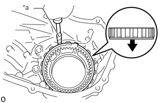
| *a | Protective Tape |
|
|
Front Side |
Install the transfer low planetary ring gear.
- NOTICE:
-
Install the transfer low planetary ring gear in the correct direction.
Using a screwdriver, install the transfer low planetary ring gear hole snap ring.
- NOTICE:
-
The transfer low planetary gear shaft snap ring should be installed completely.
- HINT:
-
Tape the screwdriver tip before use.
36111C
16.INSTALL TRANSFER CASE PLUG
Clean the transfer case plug hole.
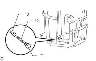
| *1 | Transfer Case Plug |
| *2 | Transfer Case Compression Spring |
| *3 | Pin |
Install the pin and transfer case compression spring.
Install a new transfer case plug.
- Torque:
- 18.6 N*m (190 kgf*cm, 14 ft.*lbf)
36270
17.INSTALL TRANSFER LOW PLANETARY GEAR ASSEMBLY
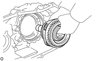
Install the transfer low planetary gear assembly.
- HINT:
-
When installation under normal temperatures is difficult, heat the front transfer case to approximately 50 to 80 °C (122 to 176 °F), and then install it.
- CAUTION:
-
Be careful not to burn yourself when the front transfer case temperature is high.
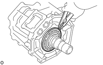
Using a snap ring expander, install the transfer low planetary gear bearing shaft snap ring.
- NOTICE:
-
After installation, if there is any clearance along the inside diameter of the transfer low planetary gear bearing shaft snap ring, replace it with a new one.
36102L
18.INSTALL TRANSFER FRONT BEARING TYPE T OIL SEAL
for A750F, AC60F, R151F:
Coat the lip of a new transfer front bearing type T oil seal with MP grease.
for RC61F:
Coat the lip of 2 new transfer front bearing type T oil seals with MP grease.
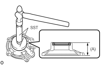
for A750F, AC60F, R151F:
Using SST and a hammer, install the transfer front bearing type T oil seal as shown in the illustration.
- SST
- 09950-60010 (09951-00410, 09951-00570, 09952-06010)
09950-70010 (09951-07100)
- Drive in depth (A):
43.0 to 44.0 mm (1.70 to 1.73 in.)
- NOTICE:
-
Be careful not to damage the transfer front bearing type T oil seal.
for RC61F:
Using SST and a hammer, install the 2 transfer front bearing type T oil seals as shown in the illustration.
- SST
- 09950-60010 (09951-00410, 09951-00570, 09952-06010)
09950-70010 (09951-07100)
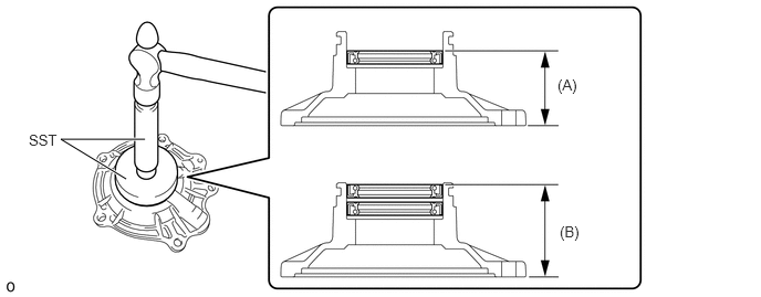
- Drive in depth:
Drive in depth (A) 43.0 to 44.0 mm (1.70 to 1.73 in.) Drive in depth (B) 53.0 to 54.0 mm (2.09 to 2.12 in.)
- NOTICE:
- ·
Install the transfer front bearing type T oil seal in the correct direction.
·Be careful not to damage the transfer front bearing type T oil seal.
36102G
19.INSTALL TRANSFER FRONT BEARING RETAINER SUB-ASSEMBLY
Clean the 5 bolt holes.
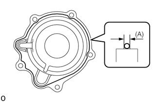
Apply seal packing to the transfer front bearing retainer sub-assembly as shown in the illustration.
- Seal packing:
Toyota Genuine Seal Packing 1281, Three Bond 1281 or equivalent
- Seal width (A):
1.2 mm (0.0472 in.)
- NOTICE:
-
If the removed transfer front bearing retainer sub-assembly will be reused: After removing the transfer front bearing retainer sub-assembly, be sure to perform the following before reinstalling it: 1) using a knife, cut off any old seal packing on the transfer front bearing retainer sub-assembly contact surface, 2) clean off any remaining old seal packing from the transfer front bearing retainer sub-assembly contact surface, and 3) reapply seal packing to the transfer front bearing retainer sub-assembly.
Apply adhesive to 2 or 3 threads on the end of the 5 new bolts.
- Adhesive:
Toyota Genuine Adhesive 1344, Three Bond 1344 or equivalent
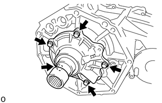
Install the transfer front bearing retainer sub-assembly with the 5 bolts.
- Torque:
- 11.5 N*m (117 kgf*cm, 8 ft.*lbf)
- NOTICE:
- ·
Tighten the bolts of the transfer front bearing retainer sub-assembly within 10 minutes of applying the seal packing.
The seal packing will dry very quickly.
·Be careful not to damage the transfer front bearing type T oil seal.
for RC61F:
Apply manual transmission oil to a new O-ring.
Install the O-ring.
- NOTICE:
- ·
Do not scratch or twist the O-ring.
·The O-ring should be installed completely.
36106
20.INSTALL TRANSFER OIL PUMP BODY SUB-ASSEMBLY
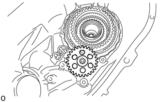
Apply transfer oil to the transfer oil pump gear.
Install the transfer oil pump gear.
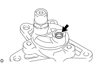
Apply transfer oil to a new transfer oil pump body O-ring.
Install the transfer oil pump body O-ring.
- NOTICE:
- ·
Do not scratch or twist the transfer oil pump body O-ring.
·The transfer oil pump body O-ring should be installed completely.
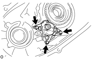
Install the transfer oil pump body sub-assembly with the 3 bolts.
- Torque:
- 7.5 N*m (76 kgf*cm, 66 in.*lbf)
36104H
21.INSTALL TRANSFER OIL SEPARATOR SUB-ASSEMBLY
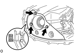
Install the transfer case magnet.
Install the transfer oil separator sub-assembly with the 3 bolts.
- Torque:
- 7.5 N*m (76 kgf*cm, 66 in.*lbf)
- NOTICE:
-
Be careful not to damage the transfer oil pump body O-ring.
36112
22.INSTALL REAR TRANSFER CASE
Apply transfer oil to the the transfer output shaft front needle roller bearing, the inside diameter of the internal bush portion of the transfer input shaft and the fitting surfaces of the high and low clutch sleeve and transfer low planetary gear assembly.
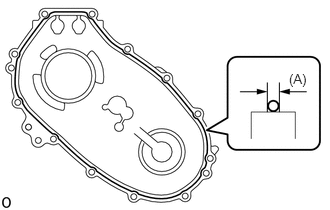
Apply seal packing to the rear transfer case as shown in the illustration.
- Seal packing:
Toyota Genuine Seal Packing 1281, Three Bond 1281 or equivalent
- Seal width (A):
1.2 mm (0.0472 in.)
- NOTICE:
-
If the removed rear transfer case will be reused: After removing the rear transfer case, be sure to perform the following before reinstalling it: 1) using a knife, cut off any old seal packing on the rear transfer case contact surface, 2) clean off any remaining old seal packing from the rear transfer case contact surface, and 3) reapply seal packing to the rear transfer case.
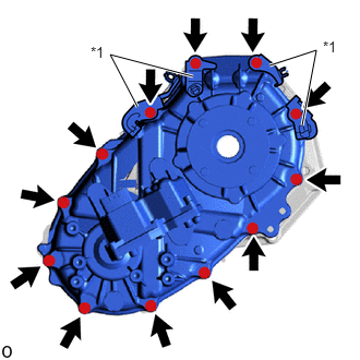
| *1 | Bracket |
Install the rear transfer case and 4 brackets with the 12 bolts.
- Torque:
- 28 N*m (286 kgf*cm, 21 ft.*lbf)
- NOTICE:
-
Tighten the bolts of the rear transfer case within 10 minutes of applying the seal packing.
-
The seal packing will dry very quickly.
33309H
23.INSTALL TRANSFER OUTPUT SHAFT WASHER
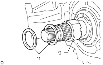
| *1 | Transfer Output Shaft Washer |
| *2 | No. 2 Transfer Output Shaft Spacer |
Install the No. 2 transfer output shaft spacer.
Install the 2 transfer output shaft washers.
36115
24.INSTALL TRANSFER EXTENSION HOUSING
Clean the 5 bolt holes.
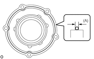
Apply seal packing to the transfer extension housing as shown in the illustration.
- Seal packing:
Toyota Genuine Seal Packing 1281, Three Bond 1281 or equivalent
- Seal width (A):
1.2 mm (0.0472 in.)
- NOTICE:
-
If the removed transfer extension housing will be reused: After removing the transfer extension housing, be sure to perform the following before reinstalling it: 1) using a knife, cut off any old seal packing on the transfer extension housing contact surface, 2) clean off any remaining old seal packing from the transfer extension housing contact surface, and 3) reapply seal packing to the transfer extension housing.
Apply adhesive to 2 or 3 threads on the end of the 5 new bolts.
- Adhesive:
Toyota Genuine Adhesive 1344, Three Bond 1344 or equivalent
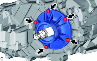
Install the transfer extension housing with the 5 bolts.
- Torque:
- 12 N*m (122 kgf*cm, 9 ft.*lbf)
- NOTICE:
-
Tighten the bolts of the transfer extension housing within 10 minutes of applying the seal packing.
-
The seal packing will dry very quickly.
36115C
25.INSTALL TRANSFER EXTENSION HOUSING TYPE T OIL SEAL
33309C
26.INSTALL OUTPUT SHAFT COMPANION FLANGE SUB-ASSEMBLY (for Rear Side)
Apply transfer oil to a new transfer output shaft O-ring and the fitting portions of the output shaft companion flange sub-assembly and rear transfer output shaft.
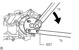
| *a | Turn |
| *b | Hold |
Using SST to hold the output shaft companion flange sub-assembly, install the transfer output shaft O-ring and a new transfer output shaft companion flange nut.
- SST
- 09330-00021
- Torque:
- 127.4 N*m (1299 kgf*cm, 94 ft.*lbf)
- NOTICE:
- ·
Do not scratch or twist the transfer output shaft O-ring.
·The transfer output shaft O-ring should be installed completely.
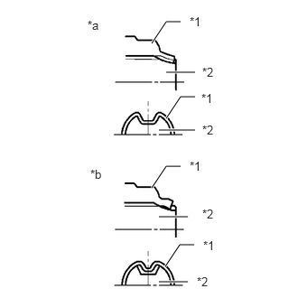
| *1 | Transfer Output Shaft Companion Flange Nut |
| *2 | Rear Transfer Output Shaft |
| *a | Correct |
| *b | Incorrect |
Using a chisel and hammer, stake the transfer output shaft companion flange nut as shown in the illustration.
36111B
27.INSTALL TRANSFER CASE OIL SEAL
33309B
28.INSTALL OUTPUT SHAFT COMPANION FLANGE SUB-ASSEMBLY (for Front Side)
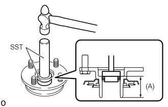
Using SST and hammer, install a new transfer output shaft companion flange oil seal.
- SST
- 09950-60010 (09951-00220, 09951-00310, 09952-06010)
09950-70010 (09951-07100)
- Drive in depth (A):
38.0 to 39.0 mm (1.50 to 1.53 in.)
- NOTICE:
-
Install the transfer output shaft companion flange oil seal in the correct direction.
Apply transfer oil to the fitting portions of the output shaft companion flange sub-assembly and transfer driven sprocket.
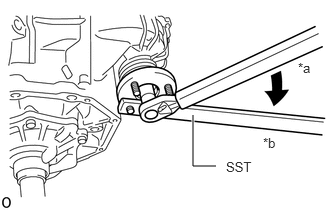
| *a | Turn |
| *b | Hold |
Using SST to hold the output shaft companion flange sub-assembly, install a new transfer output shaft companion flange nut.
- SST
- 09330-00021
- Torque:
- 118 N*m (1203 kgf*cm, 87 ft.*lbf)
| *1 | Transfer Output Shaft Companion Flange Nut |
| *2 | Rear Transfer Output Shaft |
| *a | Correct |
| *b | Incorrect |
Using a chisel and hammer, stake the transfer output shaft companion flange nut as shown in the illustration.
36114B
29.INSTALL NO. 1 TRANSFER CASE PLUG
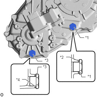
| *1 | No. 1 Transfer Case Plug (Filler Plug) |
| *2 | No. 1 Transfer Case Gasket |
| *3 | Transfer Drain Plug |
| *4 | Transfer Drain Plug Gasket |
Install a new No. 1 transfer case gasket to the No. 1 transfer case plug (filler plug), and then install the No. 1 transfer case plug (filler plug).
- Torque:
- 37 N*m (377 kgf*cm, 27 ft.*lbf)
Install a new transfer drain plug gasket to the transfer drain plug, and then install the transfer drain plug.
- Torque:
- 37 N*m (377 kgf*cm, 27 ft.*lbf)
36102
30.INSTALL TRANSFER CASE COVER SUB-ASSEMBLY
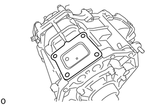
Install the breather oil deflector.
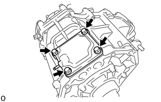
Install the transfer case cover sub-assembly with the 4 bolts.
- Torque:
- 18 N*m (184 kgf*cm, 13 ft.*lbf)
31.INSTALL ACTUATOR BREATHER HOSE
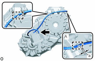
| *a | 0 to 3.0 mm |
Install the 2 clamps and actuator breather hose as shown in the illustration.
- NOTICE:
- ·
Install the actuator breather hose so that it passes between the rear transfer case and transfer shift actuator assembly.
·Fully install the actuator breather hose to the base of the transfer shift actuator assembly.
·Install the actuator breather hose so that the net protector in area A extends 0 to 3.0 mm (0 to 0.118 in.) from the clamp.