2TR-FBE FUEL FUEL SYSTEM ON-VEHICLE INSPECTION
PROCEDURE

 1.CHECK FUEL PUMP OPERATION AND INSPECT FOR FUEL LEAKS
Connect the GTS to the DLC3.
Turn the ignition switch on (IG).
- NOTICE:
-
Do not start the engine.
Turn the GTS on.
Enter the following menus: Powertrain / Engine and ECT / Active Test / Control the Fuel Pump / Speed.
- Powertrain > Engine and ECT > Active Test
-
Tester Display Control the Fuel Pump / Speed - 50004 234 5
Check fuel pump operation.
Check for pressure in the fuel inlet tube from the fuel line. Check that the sound of fuel flowing in the fuel tank can be heard.
If there is no sound, check the instrument panel junction block, fuel pump, ECM and wiring connector.
Inspect for fuel leaks.
Check that there are no fuel leaks after performing maintenance anywhere on the system.
If there are fuel leaks, repair or replace parts as necessary.
2.CHECK FUEL PRESSURE
Check the battery voltage.
Click herePower Source / Network>2TR-FBE BATTERY / CHARGING>CHARGING SYSTEM>ON-VEHICLE INSPECTION
Discharge the fuel system pressure.
Click hereEngine / Hybrid System>2TR-FBE FUEL>FUEL SYSTEM>PRECAUTION
Disconnect the cable from the negative (-) battery terminal.
- NOTICE:
- ·
After turning the ignition switch off, waiting time may be required before disconnecting the cable from the battery terminal. Therefore, make sure to read the disconnecting the cable from the battery terminal notice before proceeding with work.
Click hereGeneral>INTRODUCTION>REPAIR INSTRUCTION>PRECAUTION
·When disconnecting the cable, some systems need to be initialized after the cable is reconnected.
Click hereGeneral>INTRODUCTION>REPAIR INSTRUCTION>INITIALIZATION
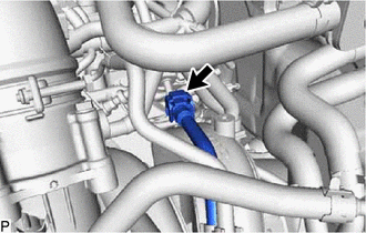
Disconnect the No. 1 fuel hose.
Click hereEngine / Hybrid System>2TR-FBE FUEL>FUEL SYSTEM>PRECAUTION
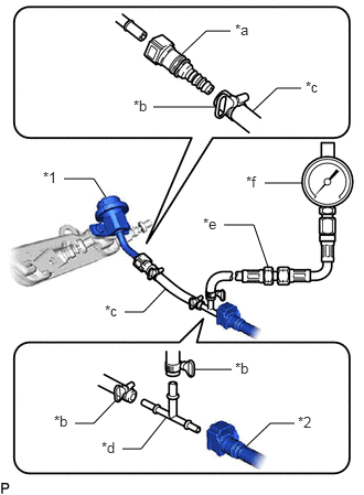
| *1 | Fuel Pressure Pulsation Damper Assembly |
| *2 | No. 1 Fuel Hose |
| *a | SST (Fuel Tube Connector) |
| *b | SST (Hose Band) |
| *c | SST (Hose) |
| *d | SST (T-Joint) |
| *e | SST (Hose Joint) |
| *f | SST (Gauge) |
Install SST (pressure gauge) as shown in the illustration.
- SST
- 09268-45101 (09268-41250, 09268-41260, 09268-41280, 09268-41500, 09268-41700, 95336-08070)
Wipe off any gasoline.
Reconnect the cable to the negative (-) battery terminal.
- NOTICE:
-
When disconnecting the cable, some systems need to be initialized after the cable is reconnected.
-
Click hereGeneral>INTRODUCTION>REPAIR INSTRUCTION>INITIALIZATION
Operate the fuel pump.
Connect the GTS to the DLC3.
Turn the ignition switch on (IG).
- NOTICE:
-
Do not start the engine.
Turn the GTS on.
Enter the following menus: Powertrain / Engine and ECT / Active Test / Control the Fuel Pump / Speed.
- Powertrain > Engine and ECT > Active Test
-
Tester Display Control the Fuel Pump / Speed - 50004 234 5
Measure the fuel pressure.
- Standard fuel pressure:
330 to 370 kPa (3.4 to 3.8 kgf/cm2, 48 to 54 psi)
If the pressure is higher than the specification, replace the fuel pressure regulator.
If the pressure is below the specification, check the fuel hoses and connectors, fuel pump, fuel filter and fuel pressure regulator.
Start the engine.
Measure the fuel pressure.
- Standard fuel pressure:
330 to 370 kPa (3.4 to 3.8 kgf/cm2, 48 to 54 psi)
If the pressure is not as specified, check the fuel pump, pressure regulator and/or injectors.
Stop the engine.
Check that the fuel pressure remains as specified for 5 minutes after the engine has stopped.
- Standard fuel pressure:
147 kPa (1.5 kgf/cm2, 21 psi) or higher
If the pressure is not as specified, check the fuel pump, pressure regulator and/or injectors.
Disconnect the cable from the negative (-) battery terminal and carefully remove SST and the fuel tube connector to prevent gasoline from spraying.
Connect the No. 1 fuel hose.
Click hereEngine / Hybrid System>2TR-FBE FUEL>FUEL SYSTEM>PRECAUTION
Inspect for fuel leaks.
Click hereEngine / Hybrid System>2TR-FBE FUEL>FUEL INJECTOR>INSTALLATION
3.CHECK GLOW PLUG
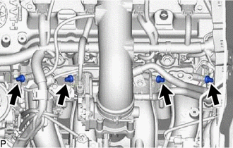
Remove the 4 glow plug screw grommets.
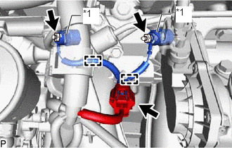
| *1 | Fuel Pipe Support |
Remove the 2 nuts.
Disconnect the wire harness connector.
Detach the 2 wire harness clamps and remove the No. 1 glow plug connector.
Remove the 2 fuel pipe supports.
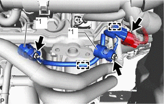
| *1 | Fuel Pipe Support |
Remove the 2 nuts.
Disconnect the wire harness connector.
Detach the 2 wire harness clamps and remove the No. 2 glow plug connector.
Remove the 2 fuel pipe supports.
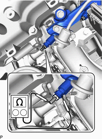
Measure the resistance according to the value(s) in the table below.
- Standard Resistance:
Tester Connection Condition Specified Condition Glow plug terminal - Body ground 20°C (68°F) Approximately 1.0 Ω
If the result is not as specified, replace the glow plug assembly.
- NOTICE:
- ·
Be careful not to damage the glow plug assemblies, as this may cause an open circuit or shorten the life of the glow plug assemblies.
·Do not allow oil or gasoline to contact the glow plug assembly when cleaning it.
·Clean off any oil on the terminal with a dry cloth.
·Do not apply more than 11 V to the glow plug assembly, as this may cause an open circuit.
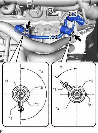
| *a | Rib |
| *b | 170 to 190° |
| *c | 40 to 60° |
| *1 | Wire Harness |
| *2 | FueL Pipe Support |
| *3 | Glow Plug Assembly |
Install the 2 fuel pipe supports to each glow plug assembly as shown in the illustration.
Connect the No. 2 glow plug connector to each glow plug assembly and install with the 2 nuts as shown in the illustration.
- Torque:
- 2.2 N*m (22 kgf*cm, 19 in.*lbf)
Connect the wire harness connector.
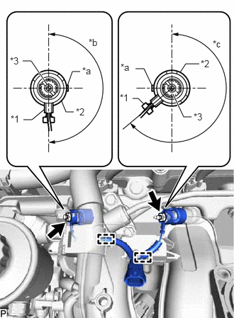
| *a | Rib |
| *b | 170 to 190° |
| *c | 220 to 240° |
| *1 | Wire Harness |
| *2 | FueL Pipe Support |
| *3 | Glow Plug Assembly |
Install the 2 fuel pipe supports to each glow plug assembly as shown in the illustration.
Connect the No. 1 glow plug connector to each glow plug assembly and install with the 2 nuts as shown in the illustration.
- Torque:
- 2.2 N*m (22 kgf*cm, 19 in.*lbf)
Connect the wire harness connector.
Install the 4 glow plug screw grommets.