RM3250E
_51
Engine / Hybrid System
_037981
1GR-FE ENGINE CONTROL
_0176375
KNOCK SENSOR
A
1GR-FE ENGINE CONTROL KNOCK SENSOR INSTALLATION
PROCEDURE

 1.INSTALL KNOCK SENSOR
- HINT:
-
Perform "Inspection After Repairs" after replacing the knock sensor.
-
Click hereEngine / Hybrid System>1GR-FE ENGINE CONTROL>SFI SYSTEM>INITIALIZATION
a.
0.417,0.292 0.646,0.49
0.229,0.198
10
false
*A
0.427,3.24 0.74,3.396
0.313,0.156
10
false
*B
0.51,0.802 0.708,1
0.198,0.198
10
false
*a
1.375,0.281 1.573,0.469
0.198,0.188
10
false
*b
0.521,3.708 0.708,3.906
0.188,0.198
10
false
*c
2.708,1 2.906,1.188
0.198,0.188
10
false
*d
2.719,3.896 2.906,4.094
0.188,0.198
10
false
*d
1.385,3.208 1.573,3.396
0.188,0.188
10
false
*b
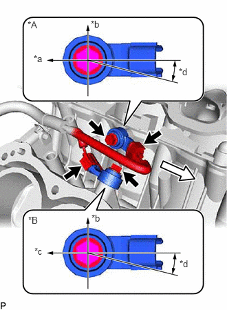
| *A | for Bank 2 |
| *B | for Bank 1 |
| *a | Engine Rear |
| *b | Top |
| *c | Engine Front |
| *d | 0 to 15° |
Install the 2 knock sensors with the 2 bolts as shown in the illustration.
- Torque:
- 20 N*m (204 kgf*cm, 15 ft.*lbf)
b.
Connect the 2 knock sensor connectors.
16332
2.INSTALL NO. 1 WATER OUTLET PIPE
a.
for Type A:
Install the No. 1 water outlet pipe with the 3 bolts.
- Torque:
- 10 N*m (102 kgf*cm, 7 ft.*lbf)
b.
for Type B:
Install the No. 1 water outlet pipe with the 2 nuts and bolt.
- Torque:
- 10 N*m (102 kgf*cm, 7 ft.*lbf)
c.
Attach the 3 wire harness clamps.
11101
3.INSTALL CYLINDER HEAD SUB-ASSEMBLY RH (for Bank 1)