RM3250E
_51
Engine / Hybrid System
_037982
1GR-FE ENGINE MECHANICAL
_0177657
CYLINDER BLOCK
A
1GR-FE ENGINE MECHANICAL CYLINDER BLOCK REPLACEMENT
PROCEDURE

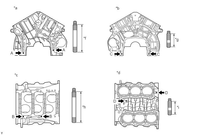
 1.REPLACE STUD BOLT
- NOTICE:
-
If a stud bolt is deformed or its threads are damaged, replace it.
a.
Using an E5, E7 and E8 "TORX" wrench, remove the stud bolts.
b.
Using an E5, E7 and E8 "TORX" wrench, install new stud bolts.
0.49,0.198 0.698,0.417
0.208,0.219
10
false
*a
4.146,0.208 4.323,0.417
0.177,0.208
10
false
*b
0.521,2.594 0.708,2.781
0.188,0.188
10
false
*c
4.177,2.51 4.354,2.708
0.177,0.198
10
false
*d
2.99,1.281 3.156,1.458
0.167,0.177
10
false
*f
6.271,1.323 6.458,1.573
0.188,0.25
10
false
*g
2.948,3.74 3.135,3.927
0.188,0.188
10
false
*h
6.333,3.75 6.51,3.938
0.177,0.188
10
false
*i
0.375,1.813 0.531,2.01
0.156,0.198
10
true
A
2.24,1.698 2.396,1.896
0.156,0.198
10
true
A
0.427,4.083 0.563,4.281
0.135,0.198
10
true
B
1.771,4.073 1.927,4.271
0.156,0.198
10
true
B
3.938,1.844 4.094,2.042
0.156,0.198
10
true
C
5.625,1.854 5.781,2.052
0.156,0.198
10
true
C
4.063,3.531 4.219,3.729
0.156,0.198
10
true
D
5.917,3.229 6.073,3.427
0.156,0.198
10
true
D
| *a | Front Side | *b | Rear Side |
| *c | Lower Side | *d | Upper Side |
| *f | 52 mm (2.05 in.) | *g | 23 mm (0.906 in.) |
| *h | 55 mm (2.17 in.) | *i | 18 mm (0.709 in.) |
- Torque:
- for stud bolt A and B : 11 N*m (112 kgf*cm, 8 ft.*lbf)
- for stud bolt C and D : 4.0 N*m (41 kgf*cm, 35 in.*lbf)
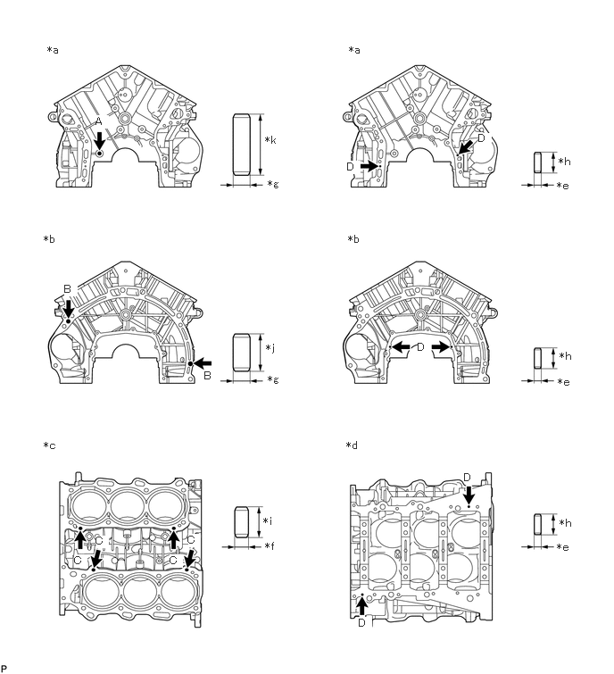
2.REPLACE STRAIGHT PIN
- NOTICE:
-
It is not necessary to remove the straight pin unless it is being replaced.
a.
Remove the straight pins.
b.
Using a plastic-faced hammer, tap new straight pins into the cylinder block.
0.552,0.51 1.271,0.667
0.719,0.156
10
false
*a
0.51,2.719 1.229,2.875
0.719,0.156
10
false
*b
0.51,5.125 1.292,5.281
0.781,0.156
10
false
*c
4.042,5.125 4.833,5.281
0.792,0.156
10
false
*d
4.063,2.719 4.781,2.875
0.719,0.156
10
false
*b
4.073,0.51 4.792,0.667
0.719,0.156
10
false
*a
3.125,2.073 3.375,2.323
0.25,0.25
10
false
*g
3.125,4.354 3.323,4.583
0.198,0.229
10
false
*g
3.094,6.302 3.375,6.531
0.281,0.229
10
false
*f
3.073,6.01 3.302,6.198
0.229,0.188
10
false
*i
6.531,6.031 6.854,6.219
0.323,0.188
10
false
*h
6.531,4.083 6.802,4.25
0.271,0.167
10
false
*h
6.521,1.813 6.781,2
0.26,0.188
10
false
*h
6.5,6.313 6.719,6.583
0.219,0.271
10
false
*e
6.51,4.385 6.781,4.667
0.271,0.281
10
false
*e
6.5,2.094 6.844,2.354
0.344,0.26
10
false
*e
3.104,3.99 3.24,4.208
0.135,0.219
10
false
*j
3.094,1.563 3.677,1.875
0.583,0.313
10
false
*k
1.115,1.344 1.271,1.5
0.156,0.156
10
true
A
0.75,3.302 0.906,3.458
0.156,0.156
10
true
B
2.385,4.313 2.542,4.469
0.156,0.156
10
false
B
0.865,6.469 1.021,6.625
0.156,0.156
10
true
C
1.115,6.24 1.271,6.396
0.156,0.156
10
true
C
1.979,6.469 2.135,6.625
0.156,0.156
10
true
C
2.188,6.229 2.344,6.385
0.156,0.156
10
true
C
4.188,7.198 4.344,7.354
0.156,0.156
10
true
D
5.417,5.5 5.573,5.656
0.156,0.156
10
true
D
4.875,3.979 5.031,4.135
0.156,0.156
10
true
D
4.052,1.875 4.208,2.031
0.156,0.156
10
true
D
5.583,1.542 5.74,1.698
0.156,0.156
10
true
D
| *a | Front Side | *b | Rear Side |
| *c | Upper Side | *d | Lower Side |
| *e | 4.0 mm (0.157 in.) | *f | 8.0 mm (0.315 in.) |
| *g | 10 mm (0.394 in.) | *h | 12 mm (0.472 in.) |
| *i | 18 mm (0.709 in.) | *j | 22 mm (0.866 in.) |
| *k | 36 mm (1.42 in.) | - | - |
- Standard Protrusion Height:
Item Specified Condition Pin A 22.5 to 23.5 mm (0.886 to 0.925 in.) Pin B 10.5 to 11.5 mm (0.413 to 0.453 in.) Pin C 8.5 to 9.5 mm (0.335 to 0.374 in.) Pin D 5.5 to 6.5 mm (0.217 to 0.256 in.)
13516
3.REPLACE OIL JET
- NOTICE:
-
It is not necessary to remove the oil jet unless it is being replaced.
a.
Using a screwdriver and hammer, tap out the oil jet.
b.
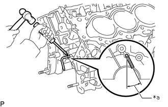
3.094,2 2.906,2
2.906,2 2.74,1.74
true
3.135,1.917 3.396,2.094
0.26,0.177
10
false
*a
| *a | 21.5 to 31.5° |
Using a screwdriver and hammer, tap in a new oil jet as shown in the illustration.