1GR-FE FUEL FUEL INJECTOR REMOVAL
CAUTION / NOTICE / HINT
The necessary procedures (adjustment, calibration, initialization, or registration) that must be performed after parts are removed, installed, or replaced during the fuel injector assembly removal/installation are shown below.
| Replacement Part or Procedure | Necessary Procedures | Effects/Inoperative when not Performed | Link |
|---|---|---|---|
| Replacement of fuel injector assembly | Inspection after repair | Poor idle, engine start function, etc. | ( ) |
PROCEDURE

 1.DISCHARGE FUEL SYSTEM PRESSURE
2. PRECAUTION
- NOTICE:
-
After turning the ignition switch off, waiting time may be required before disconnecting the cable from the battery terminal. Therefore, make sure to read the disconnecting the cable from the battery terminal notice before proceeding with work.
-
Click hereGeneral>INTRODUCTION>REPAIR INSTRUCTION>PRECAUTION
3.DISCONNECT CABLE FROM NEGATIVE BATTERY TERMINAL
- NOTICE:
-
When disconnecting the cable, some systems need to be initialized after the cable is reconnected.
-
Click hereGeneral>INTRODUCTION>REPAIR INSTRUCTION>INITIALIZATION
17129
4.REMOVE INTAKE AIR SURGE TANK
23801P
5.DISCONNECT NO. 1 FUEL PIPE SUB-ASSEMBLY
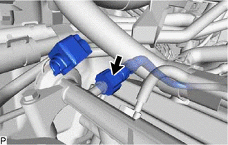
Remove the No. 2 fuel pipe clamp and disconnect the No. 1 fuel pipe sub-assembly from the fuel delivery pipe sub-assembly.
Click hereEngine / Hybrid System>1GR-FE FUEL>FUEL SYSTEM>PRECAUTION
23802B
6.DISCONNECT NO. 2 FUEL PIPE SUB-ASSEMBLY
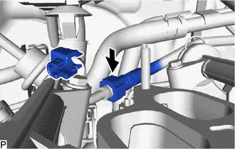
Remove the No. 2 fuel pipe clamp and disconnect the No. 2 fuel pipe sub-assembly from the fuel pressure regulator assembly.
Click hereEngine / Hybrid System>1GR-FE FUEL>FUEL SYSTEM>PRECAUTION
23807
7.REMOVE FUEL DELIVERY PIPE SUB-ASSEMBLY
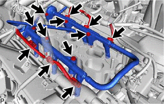
Disconnect the 6 fuel injector assembly connectors from the 6 fuel injector assemblies.
Remove the 6 bolts and fuel delivery pipe sub-assembly together with the 6 fuel injector assemblies.
- NOTICE:
-
Be careful not to drop the fuel injector assembly when removing the fuel delivery pipe sub-assembly.
23250
8.REMOVE FUEL INJECTOR ASSEMBLY
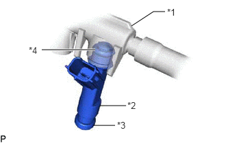
| *1 | Fuel Delivery Pipe Sub-assembly |
| *2 | Fuel Injector Assembly |
| *3 | Fuel Vibration Insulator |
| *4 | O-RING |
Remove the 6 fuel injector assemblies from the fuel delivery pipe sub-assembly.
Remove the O-ring and fuel vibration insulator from each fuel injector assembly.