EXTERIOR PANELS / TRIM FRONT BUMPER(for Resin Type Bumper) INSTALLATION
CAUTION / NOTICE / HINT
- HINT:
-
A bolt without a torque specification is shown in the standard bolt chart.
-
Click hereGeneral>SPECIFICATIONS>STANDARD BOLT>SPECIFIED TORQUE FOR STANDARD BOLTS
PROCEDURE

 52116A
1.INSTALL FRONT BUMPER SIDE SUPPORT LH (for Standard Body)
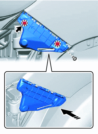

|
Install in this Direction |
Attach the claw to install the front bumper side support LH as shown in the illustration.
Install the 2 clips and bolt.
52115A
2.INSTALL FRONT BUMPER SIDE SUPPORT RH (for Standard Body)
- HINT:
-
Use the same procedure described for the LH side.
52116A
3.INSTALL FRONT BUMPER SIDE SUPPORT LH (for Wide Body)
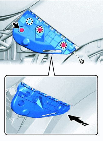
|
|
Install in this Direction |
Attach the claw to install the front bumper side support LH as shown in the illustration.
Install the 3 clips and bolt.
52115A
4.INSTALL FRONT BUMPER SIDE SUPPORT RH (for Wide Body)
- HINT:
-
Use the same procedure described for the LH side.
52021
5.INSTALL FRONT BUMPER REINFORCEMENT SUB-ASSEMBLY
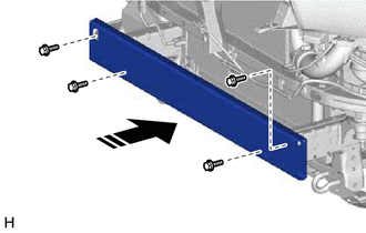
|
|
Install in this Direction |
Install the front bumper reinforcement sub-assembly with the 4 bolts.
- Torque:
- 26 N*m (265 kgf*cm, 19 ft.*lbf)
52601
6.INSTALL FRONT BUMPER ENERGY ABSORBER SUB-ASSEMBLY (w/ Energy Absorber)
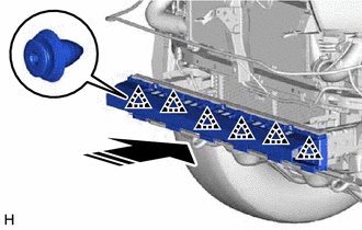
|
|
Install in this Direction |
Attach the clip to install the front bumper energy absorber sub-assembly as shown in the illustration.
53163A
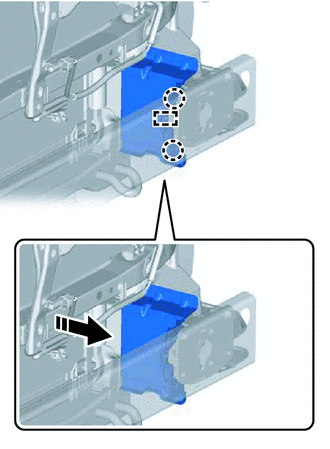
7.INSTALL FRONT BUMPER STONE DEFLECTOR LH
|
|
Install in this Direction |
Attach the claw and guide to install the front bumper stone deflector LH as shown in the illustration.
53162A
8.INSTALL FRONT BUMPER STONE DEFLECTOR RH
- HINT:
-
Use the same procedure described for the LH side.
52678
9.INSTALL FRONT BUMPER NO. 2 SIDE SUPPORT LH (w/ Energy Absorber)
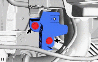
Install the front bumper side support LH with the 2 bolts.
52677
10.INSTALL FRONT BUMPER NO. 2 SIDE SUPPORT RH (w/ Energy Absorber)
- HINT:
-
Use the same procedure described for the LH side.
53294C
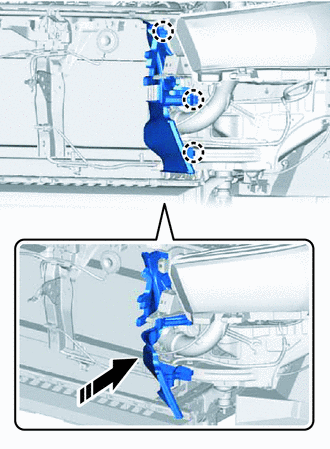
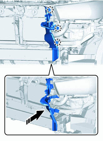
11.INSTALL RADIATOR SIDE DEFLECTOR LH
|
|
Install in this Direction |
w/ Intercooler, w/ Energy Absorber:
Attach the claw to install the radiator side deflector LH as shown in the illustration.
|
|
Install in this Direction |
w/ Intercooler, w/o Energy Absorber:
Attach the claw to install the radiator side deflector LH as shown in the illustration.
|
|
Install in this Direction |
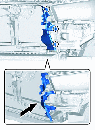
w/o Intercooler, w/ Energy Absorber:
Attach the claw to install the radiator side deflector LH as shown in the illustration.
|
|
Install in this Direction |
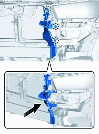
w/o Intercooler, w/o Energy Absorber:
Attach the claw to install the radiator side deflector LH as shown in the illustration.
53293C
12.INSTALL RADIATOR SIDE DEFLECTOR RH
- HINT:
-
Use the same procedure described for the LH side.
52614
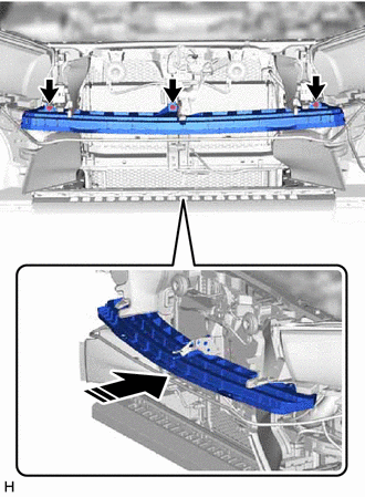
13.INSTALL FRONT BUMPER NO. 2 ENERGY ABSORBER (w/ Energy Absorber)
|
|
Install in this Direction |
Install the front bumper No. 2 energy absorber with the 3 bolts as shown in the illustration.
52119A
14.INSTALL FRONT BUMPER COVER
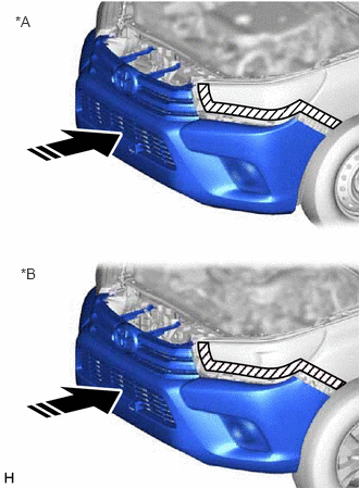
| *A | for Standard Body |
| *B | for Wide Body |
|
|
Install in this Direction |
Install the front bumper cover as shown in the illustration.
w/ Fog Light:
Connect the connector.
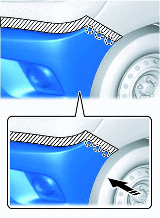
|
|
Install in this Direction |
for Standard Body:
Attach the claw as shown in the illustration.
- HINT:
-
Use the same procedure for the claw on the other side.
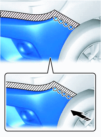
|
|
Install in this Direction |
for Wide Body:
Attach the claw as shown in the illustration.
- HINT:
-
Use the same procedure for the claw on the other side.
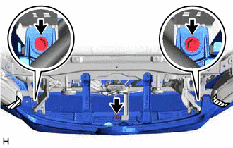
w/o Energy Absorber:
Install the 3 screws.
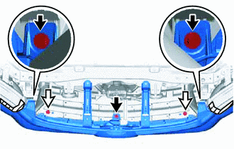

|
Screw |

|
Clip |
w/ Energy Absorber:
Install the 3 screws and 2 clips.
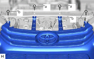
| *a | Bolt |
| *b | Screw |
Install the 2 screws and 2 bolts.
- Torque:
- for bolt : 12 N*m (122 kgf*cm, 9 ft.*lbf)
Remove the protective tape.
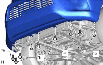
| *a | Bolt |
| *b | Screw |
Install the 6 screws and 3 bolts.
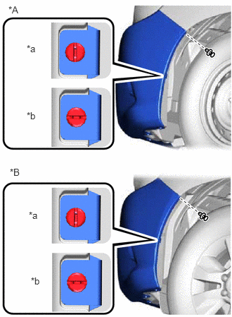
| *A | for Standard Body |
| *B | for Wide Body |
| *a | CORRECT |
| *b | INCORRECT |
Install the pin hold clip.
- HINT:
-
Use the same procedure for the pin hold clip on the other side.
Install the clip.
- HINT:
-
Use the same procedure for the clip on the other side.
53117C
15.INSTALL NO. 1 RADIATOR GRILLE RETAINER
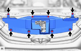
Install the No. 1 radiator grille retainer with the 8 clips.
16.ADJUST FOG LIGHT AIMING