WIPER / WASHER WIPER AND WASHER SYSTEM TERMINALS OF ECU
CHECK HEADLIGHT LEVELING ECU ASSEMBLY (w/ Headlight Cleaner System)
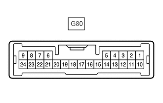
Disconnect the G80 headlight leveling ECU assembly connector.
Measure the resistance and voltage according to the value(s) in the table below.
- HINT:
-
Measure the values on the wire harness side with the connector disconnected.
| Terminal No. (Symbol) | Wiring Color | Terminal Description | Condition | Specified Condition |
|---|---|---|---|---|
| G80-1 (IG) - Body ground | G - Body ground | IG power supply | Ignition switch ON | Below 1 V |
| Ignition switch off | 11 to 14 V | |||
| G80-9 (E1) - Body ground | W-B - Body ground | Body ground | Always | Below 1 Ω |
Reconnect the G80 headlight leveling ECU assembly connector.
Measure the voltage according to the value(s) in the table below.
| Terminal No. (Symbol) | Wiring Color | Terminal Description | Condition | Specified Condition |
|---|---|---|---|---|
| G80-16 (HLC) - Body ground | B - Body ground | Headlight cleaner motor operation signal | Headlight cleaner motor not operating | 11 to 14 V |
| Headlight cleaner motor operating | Below 1 V | |||
| G80-4 (FRWA) - Body ground | LA-B - Body ground | Washer switch operation signal | Ignition switch ON, windshield wiper switch assembly (windshield washer switch) off | 11 to 14 V |
| Ignition switch ON, windshield wiper switch assembly (windshield washer switch) on | Below 1 V |
CHECK HEADLIGHT CLEANER CONTROL RELAY (w/ Headlight Cleaner System)
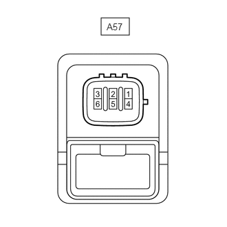
Disconnect the A57 headlight cleaner control relay connector.
Measure the voltage and resistance according to the value(s) in the table below.
- HINT:
-
Measure the values on the wire harness side with the connector disconnected.
| Terminal No. (Symbol) | Wiring Color | Terminal Description | Condition | Specified Condition |
|---|---|---|---|---|
| A57-3 (IG) - A57-4 (E) | P - W-B | IG power supply | Ignition switch ON | 11 to 14 V |
| Ignition switch off | Below 1 V | |||
| A57-4 (E) - Body ground | W-B - Body ground | Body ground | Always | Below 1 Ω |
Reconnect the A57 headlight cleaner control relay connector.
Measure the voltage according to the value(s) in the table below.
| Terminal No. (Symbol) | Wiring Color | Terminal Description | Condition | Specified Condition |
|---|---|---|---|---|
| A57-6 (PB) - A57-4 (E) | L - W-B | Headlight cleaner motor operation signal | Headlight cleaner motor not operating | 11 to 14 V |
| Headlight cleaner motor operating | Below 1 V |
CHECK COMBINATION METER ASSEMBLY (w/ Washer Fluid Level Warning System)
Disconnect the G9 and G10 combination meter assembly connectors.
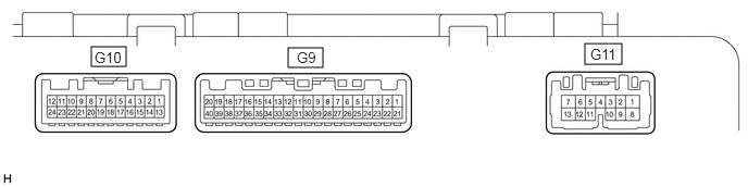
Measure the resistance and voltage according to the value(s) in the table below.
- HINT:
-
Measure the values on the wire harness side with the connector disconnected.
| Terminal No. (Symbol) | Wiring Color | Terminal Description | Condition | Specified Condition |
|---|---|---|---|---|
| G9-22 (IG+) - Body ground | Y - Body ground | IG power supply | Ignition switch ON | Below 1 V |
| Ignition switch off | 11 to 14 V | |||
| G9-21 (B) - Body ground | W - Body ground | Battery | Always | 11 to 14 V |
| G10-20 (GND) - Body ground | W-B - Body ground | Body ground | Always | Below 1 Ω |
Reconnect the G9 and G10 combination assembly connectors.
Measure the voltage according to the value(s) in the table below.
| Terminal No. (Symbol) | Wiring Color | Terminal Description | Condition | Specified Condition |
|---|---|---|---|---|
| G9-17 (WLVL) - Body ground | R - Body ground | Washer fluid level signal | Ignition switch ON, washer fluid level not low | 11 to 14 V |
| Ignition switch ON, washer fluid level low | Below 1 V |