SEAT REAR SEAT ASSEMBLY(for Seat Cushion 60/40 Split Type) REASSEMBLY
CAUTION / NOTICE / HINT
- CAUTION:
-
Wear protective gloves. Sharp areas on the parts may injure your hands.
PROCEDURE

 71485C
1.INSTALL REAR SEAT HINGE COVER RH
- NOTICE:
- ·
Perform the following only when replacing the rear seat hinge cover RH.
·Do not reuse the rear seat hinge cover RH after removing it.
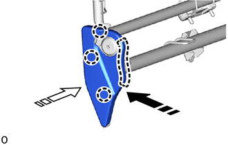

|
Install in this Direction (1) |

|
Install in this Direction (2) |
Push in installation direction (1) shown in the illustration to attach the guide.
Push in installation direction (2) shown in the illustration to attach the claw to install a new rear seat hinge cover RH.
71486C
2.INSTALL REAR SEAT HINGE COVER LH
- NOTICE:
- ·
Perform the following only when replacing the rear seat hinge cover LH.
·Do not reuse the rear seat hinge cover LH after removing it.
- HINT:
-
Use the same procedure described for the RH side.
78950
3.INSTALL NO. 1 FOLD SEAT STOPPER BAND ASSEMBLY
- HINT:
-
Use the same procedure for the opposite side.
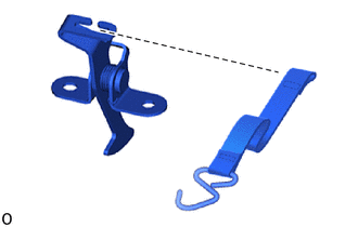
Install the No. 1 fold seat stopper band assembly to the rear No. 2 seat lock assembly.
72630F
4.INSTALL REAR NO. 2 SEAT LOCK ASSEMBLY
- HINT:
-
Use the same procedure for the opposite side.
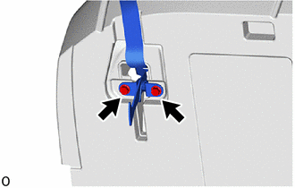
Install the rear No. 2 seat lock assembly together with the No. 1 fold seat stopper band assembly with the 2 bolts.
- Torque:
- 13 N*m (133 kgf*cm, 10 ft.*lbf)
71303C
5.INSTALL REAR SEATBACK HINGE SUB-ASSEMBLY RH
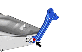
Attach the guide to install the rear seatback hinge sub-assembly RH with the bolt.
- Torque:
- 43 N*m (438 kgf*cm, 32 ft.*lbf)
71304C
6.INSTALL REAR SEATBACK HINGE SUB-ASSEMBLY LH
- HINT:
-
Use the same procedure described for the RH side.
72995B
7.INSTALL NO. 1 SEAT CUSHION COVER RH
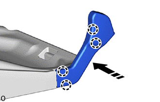
|
|
Install in this Direction |
Attach the claw to install the No. 1 seat cushion cover RH.
72998A
8.INSTALL NO. 1 SEAT CUSHION COVER LH
- HINT:
-
Use the same procedure described for the RH side.
79102
9.INSTALL NO. 1 SEAT CUSHION FRAME SUB-ASSEMBLY LH
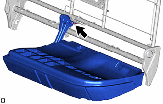
Install the No. 1 seat cushion frame sub-assembly LH together with the No. 1 seatback hinge sub-assembly LH with the nut.
- Torque:
- 13 N*m (133 kgf*cm, 10 ft.*lbf)
79101B
10.INSTALL NO. 1 SEAT CUSHION FRAME SUB-ASSEMBLY RH
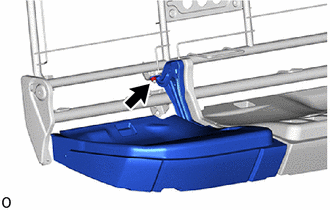
Install the No. 1 seat cushion frame sub-assembly RH together with the No. 1 seatback hinge sub-assembly RH with the nut.
- Torque:
- 13 N*m (133 kgf*cm, 10 ft.*lbf)
71223
11.INSTALL REAR SEAT CUSHION SIDE BRACKET RH
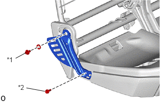
| *1 | Bolt A |
| *2 | Bolt B |
Install the rear seat cushion side bracket RH with the bush and 2 bolts.
- Torque:
- for Bolt A : 13 N*m (133 kgf*cm, 10 ft.*lbf)
- for Bolt B : 43 N*m (438 kgf*cm, 32 ft.*lbf)
71223
12.INSTALL REAR SEAT CUSHION SIDE BRACKET LH
- HINT:
-
Use the same procedure described for the RH side.
72995
13.INSTALL REAR SEAT CUSHION COVER RH
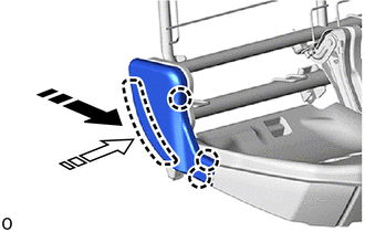
|
|
Install in this Direction (1) |
|
|
Install in this Direction (2) |
Push in installation direction (1) shown in the illustration to attach the guide.
Push in installation direction (2) shown in the illustration to attach the claw to install the rear seat cushion cover RH.
72998B
14.INSTALL REAR SEAT CUSHION COVER LH
- HINT:
-
Use the same procedure described for the RH side.
15.INSTALL SEAT COVER WIRE
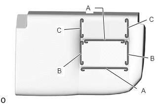
Install the seat cover wire.
- HINT:
- ·
Wire 1000 mm (3.28 ft.) or longer and shaped wire are available as supplied parts.
·For wire 1000 mm (3.28 ft.) or less in length, cut or shape 1000 mm (3.28 ft.) wire into the dimensions shown in the illustration.
·Make sure to read the precautions before preparing the wire.
Click hereVehicle Interior>SEAT>FRONT SEAT ASSEMBLY(for Manual Seat)>PRECAUTION
- Dimensions:
A 270 mm (10.63 in.) B 180 mm (7.09 in.) C 120 mm (4.72 in.)
- HINT:
-
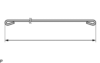
-
The dimensions shown in the illustration are the lengths.
79012
16.INSTALL NO. 1 SEAT CUSHION COVER SUB-ASSEMBLY LH
- HINT:
- ·
When installing the seat cover, refer to the precautions in order to prevent wrinkles from forming.
Click hereVehicle Interior>SEAT>FRONT SEAT ASSEMBLY(for Manual Seat)>PRECAUTION
·Align the seam allowance in a single direction as shown in the illustration.
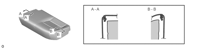 0.688,0.417 0.844,0.615 0.156,0.198 10 true A 0.885,0.552 1.042,0.75 0.156,0.198 10 true A 1.802,1.052 1.958,1.25 0.156,0.198 10 true B 2.063,1.177 2.219,1.375 0.156,0.198 10 true B 3.302,0.25 4.073,0.448 0.771,0.198 10 false A - A 5.344,0.25 6.115,0.448 0.771,0.198 10 false B - B
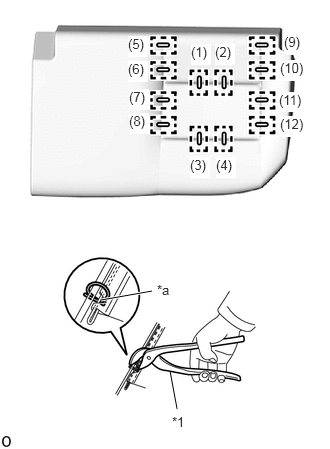
| *1 | Hog Ring Pliers |
| *a | Cutout |
Using hog ring pliers, install the No. 1 seat cushion cover sub-assembly LH to the No. 1 seat cushion pad LH with 12 new hog rings in the order indicated in the illustration.
- NOTICE:
- ·
Be careful not to damage the No. 1 seat cushion cover sub-assembly LH.
·Be sure to securely install the hog rings as shown in the illustration while preventing wrinkles from forming on the No. 1 seat cushion cover sub-assembly LH.
- HINT:
-
Install the hog rings at the cutouts if they are there.
17.INSTALL REAR SEAT CUSHION COVER WITH PAD LH
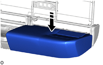
|
|
Install in this Direction |
Install the rear seat cushion cover with pad LH to the No. 1 seat cushion frame sub-assembly LH.
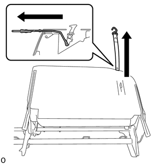
Pass the No. 1 fold seat stopper band assembly through the hole of the No. 1 seat cushion cover sub-assembly LH.
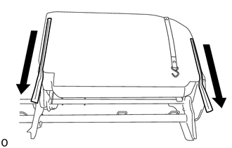
Close the 2 fasteners.
Store the 2 fasteners.
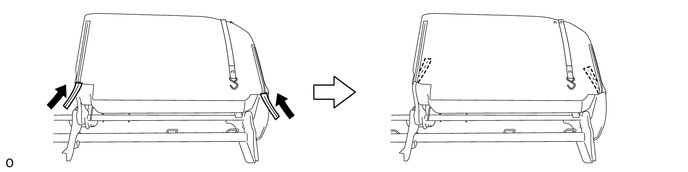
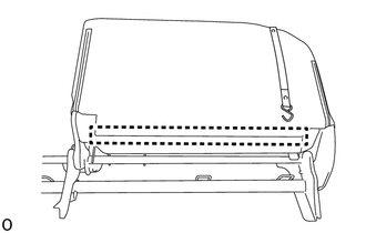
Attach the hook.
18.INSTALL SEAT COVER WIRE
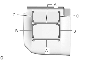
Install the seat cover wire.
- HINT:
- ·
Wire 1000 mm (3.28 ft.) or longer and shaped wire are available as supplied parts.
·For wire 1000 mm (3.28 ft.) or less in length, cut or shape 1000 mm (3.28 ft.) wire into the dimensions shown in the illustration.
·Make sure to read the precautions before preparing the wire.
Click hereVehicle Interior>SEAT>FRONT SEAT ASSEMBLY(for Manual Seat)>PRECAUTION
- Dimensions:
A 270 mm (10.63 in.) B 180 mm (7.09 in.) C 120 mm (4.72 in.)
- HINT:
-
-
The dimensions shown in the illustration are the lengths.
79011
19.INSTALL NO. 1 SEAT CUSHION COVER SUB-ASSEMBLY RH
- HINT:
- ·
When installing the seat cover, refer to the precautions in order to prevent wrinkles from forming.
Click hereVehicle Interior>SEAT>FRONT SEAT ASSEMBLY(for Manual Seat)>PRECAUTION
·Align the seam allowance in a single direction as shown in the illustration.
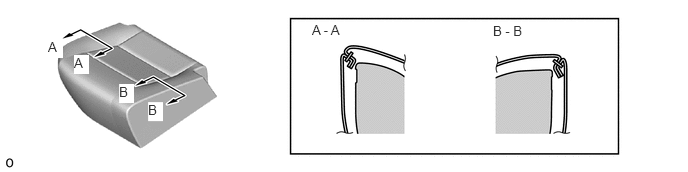 0.5,0.406 0.656,0.604 0.156,0.198 10 true A 0.771,0.573 0.927,0.771 0.156,0.198 10 true A 1.24,0.875 1.396,1.073 0.156,0.198 10 true B 1.542,1.063 1.698,1.26 0.156,0.198 10 true B 3.25,0.229 4.021,0.427 0.771,0.198 10 false A - A 5.135,0.24 5.906,0.438 0.771,0.198 10 false B - B
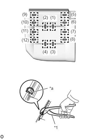
| *1 | Hog Ring Pliers |
| *a | Cutout |
Using hog ring pliers, install the No. 1 seat cushion cover sub-assembly RH to the No. 1 seat cushion pad RH with 12 new hog rings in the order indicated in the illustration.
- NOTICE:
- ·
Be careful not to damage the No. 1 seat cushion cover sub-assembly RH.
·Be sure to securely install the hog rings as shown in the illustration while preventing wrinkles from forming on the No. 1 seat cushion cover sub-assembly RH.
- HINT:
-
Install the hog rings at the cutouts if they are there.
20.INSTALL REAR SEAT CUSHION COVER WITH PAD RH
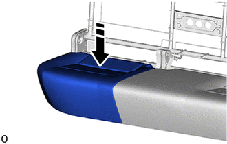
|
|
Install in this Direction |
Install the rear seat cushion cover with pad RH to the No. 1 seat cushion frame sub-assembly RH.
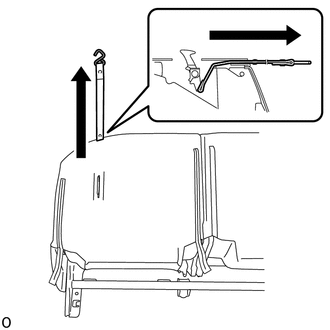
Pass the No. 1 fold seat stopper band assembly through the hole of the No. 1 seat cushion cover sub-assembly RH.
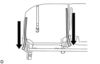
Close the 2 fasteners.
Store the 2 fasteners.
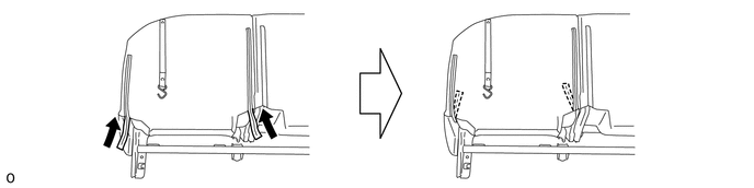
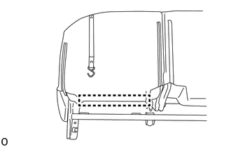
Attach the hook.
21.INSTALL SEAT COVER WIRE
Install the seat cover wire.
- HINT:
- ·
Wire 1000 mm (3.28 ft.) or longer and shaped wire are available as supplied parts.
·For wire 1000 mm (3.28 ft.) or less in length, cut or shape 1000 mm (3.28 ft.) wire into the dimensions shown in the illustration.
·Make sure to read the precautions before preparing the wire.
Click hereVehicle Interior>SEAT>FRONT SEAT ASSEMBLY(for Manual Seat)>PRECAUTION

- Dimensions:
A 270 mm (10.63 in.) B 300 mm (11.81 in.)
- HINT:
-
-
The dimensions shown in the illustration are the lengths.
79013A
22.INSTALL NO. 1 SEATBACK COVER SUB-ASSEMBLY
- HINT:
- ·
When installing the seat cover, refer to the precautions in order to prevent wrinkles from forming.
Click hereVehicle Interior>SEAT>FRONT SEAT ASSEMBLY(for Manual Seat)>PRECAUTION
·Align the seam allowance in a single direction as shown in the illustration.
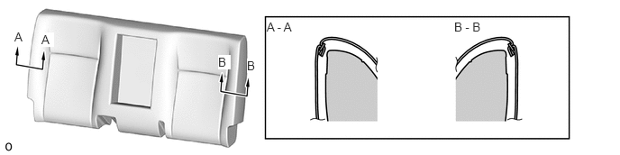 2.854,0.677 3,0.844 0.146,0.167 10 true B 0.479,0.375 0.625,0.542 0.146,0.167 10 true A 2.521,0.635 2.667,0.802 0.146,0.167 10 true B 0.167,0.344 0.313,0.51 0.146,0.167 10 true A 3.083,0.229 3.854,0.427 0.771,0.198 10 false A - A 5.25,0.229 6.021,0.427 0.771,0.198 10 false B - B
Using hog ring pliers, install the No. 1 seatback cover sub-assembly to the No. 1 seatback pad with 12 new hog rings in the order indicated in the illustration.
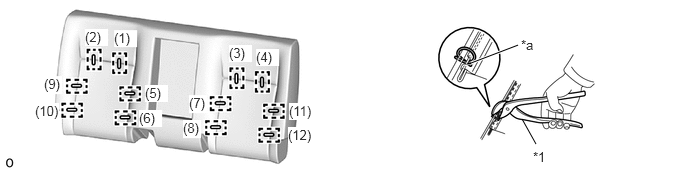
| *1 | Hog Ring Pliers | - | - |
| *a | Cutout | - | - |
- NOTICE:
- ·
Be careful not to damage the No. 1 seatback cover sub-assembly.
·Be sure to securely install the hog rings as shown in the illustration while preventing wrinkles from forming on the No. 1 seatback cover sub-assembly.
- HINT:
-
Install the hog rings at the cutouts if they are there.
23.INSTALL REAR SEATBACK COVER WITH PAD
|
|
Install in this Direction (1) |
|
|
Install in this Direction (2) |
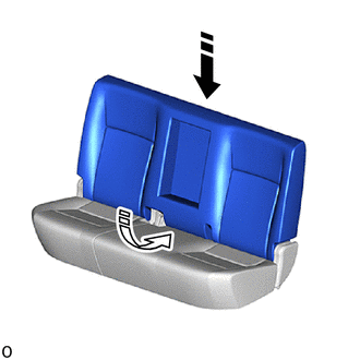
Push in installation direction (1) shown in the illustration to install the rear seatback cover with pad.
Push in the rear end of the rear seatback cover with pad in installation direction (2) shown in the illustration.
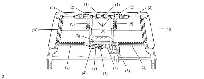
Attach the hooks in the order indicated in the illustration.
71931B
24.INSTALL REAR NO. 1 SEAT HEADREST SUPPORT ASSEMBLY
|
|
Install in this Direction |
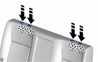
w/o Center Headrest:
Attach the claw to install the 4 rear No. 1 seat headrest support assemblies.
|
|
Install in this Direction |
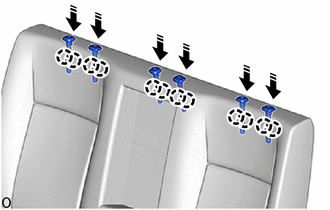
w/ Center Headrest:
Attach the claw to install the 6 rear No. 1 seat headrest support assemblies.
72806B
25.INSTALL REAR SEAT CENTER ARMREST CUP HOLDER SUB-ASSEMBLY
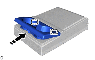
|
|
Install in this Direction |
Push as shown in the illustration to attach the guide.
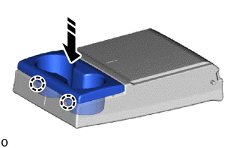
|
|
Install in this Direction |
Push as shown in the illustration to attach the claw and install the rear seat center armrest cup holder sub-assembly.
72835
26.INSTALL REAR SEAT ARMREST ARM RH
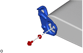
Install the rear seat armrest arm RH with the bush and bolt.
- Torque:
- 13 N*m (133 kgf*cm, 10 ft.*lbf)
72836B
27.INSTALL REAR SEAT ARMREST ARM LH
- HINT:
-
Use the same procedure described for the RH side.
72830
28.INSTALL REAR SEAT CENTER ARMREST ASSEMBLY
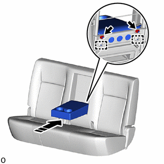
|
|
Install in this Direction |
Attach the guide to install the rear seat center armrest assembly with the 2 nuts.
- Torque:
- 13 N*m (133 kgf*cm, 10 ft.*lbf)
71960B
29.INSTALL REAR SEAT CENTER HEADREST ASSEMBLY (w/ Center Headrest)
Install the rear seat center headrest assembly.
71940A
30.INSTALL REAR SEAT HEADREST ASSEMBLY
Install the 2 rear seat headrest assemblies.
Attach the 2 No. 1 fold seat stopper band assemblies to the stay of the rear seat headrest assembly and temporarily fix the 2 rear seat cushion assemblies in place.