BRAKE SYSTEM (OTHER) LOAD SENSING PROPORTIONING VALVE(w/o ABS) REMOVAL
PROCEDURE

 1.DRAIN BRAKE FLUID
- NOTICE:
-
Wash off brake fluid immediately if it comes in contact with any painted surface.
2.DISCONNECT NO. 2 LOAD SENSING SPRING SHACKLE
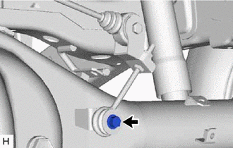
Remove the bolt, collar and 2 load sensing valve bushes.
Disconnect the No. 2 load sensing spring shackle from the rear differential.
47352B
3.REMOVE REAR FLEXIBLE HOSE BRACKET
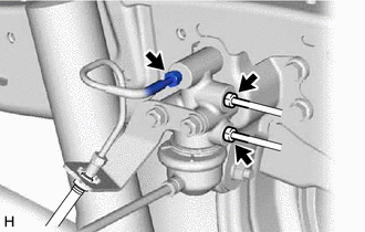
Using a union nut wrench, disconnect the 3 brake lines from the load sensing valve assembly.
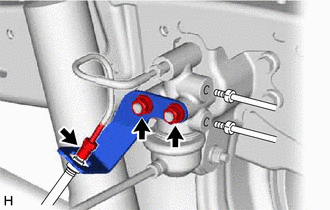
Using a union nut wrench, disconnect the rear No. 9 brake tube from the rear brake flexible hose.
Remove the clip.
Remove the 2 nuts and 2 spring washers.
Remove the rear flexible hose bracket from the load sensing valve assembly.
47931
4.REMOVE LOAD SENSING VALVE BRACKET
Remove the bolt, nut, spring washer and 2 plate washers.
Remove the 3 bolts and load sensing valve bracket.
Remove the load sensing valve set plate from the load sensing valve bracket.
5.REMOVE LOAD SENSING SPRING ASSEMBLY
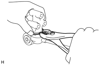
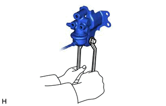
Using pliers, remove the clip and load sensing spring assembly from the load sensing valve assembly.
47935
6.REMOVE NO. 1 LOAD SENSING SPRING SHACKLE AND NO. 2 LOAD SENSING SPRING SHACKLE
Remove the bolt, nut, spring washer and 2 plate washers.
Remove the No. 1 load sensing spring shackle (with No. 2 load sensing spring shackle) from the load sensing spring assembly.
Remove the lock nut.
Remove the No. 2 load sensing spring shackle from the No. 1 load sensing spring shackle.
Remove the plate washer and adjusting nut from the No. 2 load sensing spring shackle.
04477
7.REMOVE LOAD SENSING SPRING BUSH & BOOT KIT
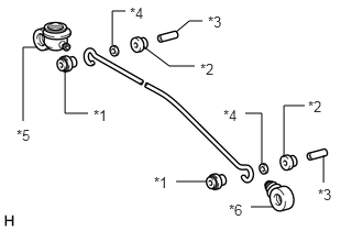
| *1 | No. 1 Load Sensing Spring Bush |
| *2 | No. 2 Load Sensing Spring Bush |
| *3 | Collar |
| *4 | Dust Seal |
| *5 | Load Sensing Valve Boot |
| *6 | Load Sensing Spring Boot |
Remove both No. 1 load sensing spring bushes, No. 2 load sensing spring bushes, collars and dust seals from the load sensing spring assembly.
Remove the load sensing valve boot and load sensing spring boot from the load sensing spring assembly.