CLUTCH CLUTCH UNIT(for RC60, RC61) INSTALLATION
PROCEDURE

 31250
1.INSTALL CLUTCH DISC ASSEMBLY
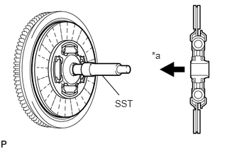
| *a | Flywheel Side |
Insert SST into the clutch disc assembly. Then insert SST (together with the clutch disc) into the flywheel.
- SST
- 09301-00110
- NOTICE:
-
Be sure to install the clutch disc so that it is facing in the correct direction.
31210
2.INSTALL CLUTCH COVER ASSEMBLY
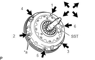
| *a | Matchmark |
Align the matchmarks on the clutch cover assembly and flywheel.
Tighten the 6 bolts as described below.
Determine the first bolt to be tightened by choosing the bolt closest to the knock pin.
Uniformly tighten the 6 bolts in diametrically opposite pairs relative to the position of the first bolt. Use the illustration as a reference.
Lightly move SST up and down, and right and left.
- SST
- 09301-00110
Check that the disc is in the center, and then tighten the bolts.
- Torque:
- 19.1 N*m (195 kgf*cm, 14 ft.*lbf)
31210
3.INSPECT AND ADJUST CLUTCH COVER ASSEMBLY
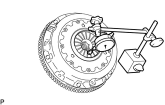
Using a dial indicator with a roller instrument, measure the diaphragm spring tip alignment.
- Maximum misalignment:
0.5 mm (0.020 in.)
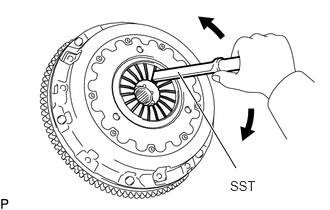
If the misalignment is more than the maximum, use SST to adjust the diaphragm spring tip alignment.
- SST
- 09333-00013
31236B
4.INSTALL RELEASE FORK SUPPORT
Install the release fork support to the manual transmission unit.
- Torque:
- 49 N*m (500 kgf*cm, 36 ft.*lbf)
31241
5.INSTALL CLUTCH RELEASE FORK DUST SEAL
Install the clutch release fork dust seal to the clutch release fork sub-assembly.
Install the clutch release fork collar to the clutch release fork sub-assembly.
31230
6.INSTALL CLUTCH RELEASE BEARING ASSEMBLY
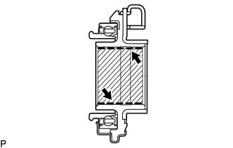

|
Multemp 8158 grease or equivalent |
Apply grease to the clutch release bearing assembly.
- Grease:
Multemp 8158 grease or equivalent
- Amount of Grease:
0.3 to 0.5 g (0.011 to 0.018 oz)
- HINT:
-
When replacing the clutch release bearing assembly with a new one, do not apply grease.
Install the release bearing hub clip to the clutch release bearing assembly.
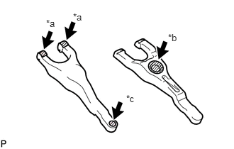
| *a | The surfaces of the release fork that contact the release bearing |
| *b | The surfaces of the release fork that contact the release fork support |
| *c | The surfaces of the release fork that contact the push rod of the release cylinder |
|
|
Multemp 8158 grease or equivalent |
Apply grease or equivalent to the following areas.
- Grease:
Multemp 8158 grease or equivalent
- Amount of Grease:
The surfaces of the release fork that contact the release bearing 1.0 to 1.3 g (0.04 to 0.05 oz) The surfaces of the release fork that contact the release fork support 1.3 to 1.8 g (0.05 to 0.06 oz) The surfaces of the release fork that contact the push rod of the release cylinder 0.5 to 0.9 g (0.02 to 0.03 oz)
Install the release fork sub-assembly to the clutch release bearing assembly.
Install the clutch release bearing assembly together with the clutch release fork sub-assembly to the clutch housing.
- NOTICE:
-
After the installation, move the fork forward and backward to check that the release bearing slides smoothly.
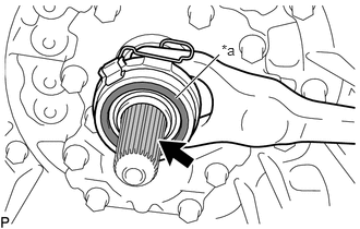
| *a | Contact surface of the bearing |
|
|
Toyota Genuine Clutch Spline Grease or equivalent |
Apply the clutch spline grease to the spline of the input shaft.
- Grease:
Toyota Genuine Clutch Spline Grease or equivalent
- NOTICE:
-
Make sure that no grease adheres to the contact surface of the bearing.
31126
7.INSTALL CLUTCH RELEASE FORK BOOT
33030
8.INSTALL MANUAL TRANSMISSION UNIT ASSEMBLY