A750F AUTOMATIC TRANSMISSION / TRANSAXLE AUTOMATIC TRANSMISSION UNIT INSPECTION
PROCEDURE

 35790
1.INSPECT NO. 2 ONE-WAY CLUTCH ASSEMBLY
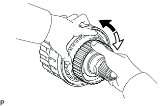
Hold the reverse clutch hub and turn the No. 2 one-way clutch assembly.

|
Lock |

|
Free |
Check that the No. 2 one-way clutch assembly turns freely clockwise and locks counterclockwise.
If there is a problem with the one-way clutch, replace the No. 2 one-way clutch assembly.
35677C
2.INSPECT REVERSE CLUTCH DISC
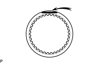
Check whether the sliding surfaces of the discs, plates or flange are worn or burnt. If necessary, replace them.
- NOTICE:
- ·
If the linings of the discs are peeled off or discolored, or if any part of the printed numbers is damaged, replace all discs.
·Before assembling new discs, soak them in ATF for at least 15 minutes.
35049
3.INSPECT REVERSE CLUTCH HUB SUB-ASSEMBLY
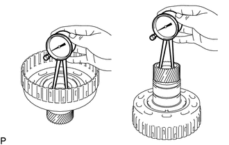
Using a dial indicator, measure the inside diameter of the reverse clutch hub bush.
- Standard inside diameter:
35.812 to 35.837 mm (1.4100 to 1.4109 in.)
- Maximum inside diameter:
35.887 mm (1.4129 in.)
If the inside diameter is more than the standard inside diameter, replace the reverse clutch hub sub-assembly.
35061
4.INSPECT FORWARD CLUTCH HUB SUB-ASSEMBLY
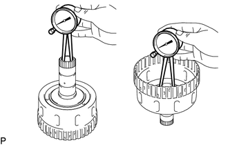
Using a dial indicator, measure the inside diameter of the forward clutch hub bush.
- Standard inside diameter:
26.037 to 26.062 mm (1.0251 to 1.0260 in.)
- Maximum inside diameter:
26.112 mm (1.0280 in.)
If the inside diameter is more than the maximum, replace the forward clutch hub sub-assembly.
35633B
5.INSPECT FORWARD MULTIPLE DISC CLUTCH DISC
Check whether the sliding surfaces of the discs, plates or flange are worn or burnt. If necessary, replace them.
- NOTICE:
- ·
If the linings of the discs are peeled off or discolored, or if any part of the printed numbers is damaged, replace all discs.
·Before assembling new discs, soak them in ATF for at least 15 minutes.
35603A
6.INSPECT FORWARD CLUTCH RETURN SPRING SUB-ASSEMBLY
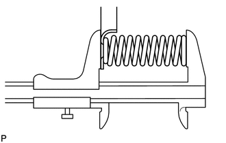
Using a vernier caliper, measure the free length of the spring together with the spring seat.
- Standard free length:
26.74 mm (1.05 in.)
If the free length is less than the standard free length, replace the forward clutch return spring sub-assembly.
35667A
7.INSPECT DIRECT CLUTCH DISC
Check whether the sliding surfaces of the discs, plates or flange are worn or burnt. If necessary, replace them.
- NOTICE:
- ·
If the linings of the discs are peeled off or discolored, or if any part of the printed numbers is damaged, replace all discs.
·Before assembling new discs, soak them in ATF for at least 15 minutes.
35047
8.INSPECT REVERSE CLUTCH RETURN SPRING SUB-ASSEMBLY
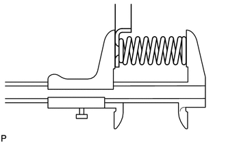
Using a vernier caliper, measure the free length of the spring together with the spring seat.
- Standard free length:
21.04 mm (0.828 in.)
If the free length is less than the standard free length, replace the reverse clutch return spring sub-assembly.
35604
9.INSPECT DIRECT CLUTCH RETURN SPRING SUB-ASSEMBLY
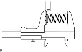
Using a vernier caliper, measure the free length of the spring together with the spring seat.
- Standard free length:
19.51 mm (0.768 in.)
If the free length is less than the standard free length, replace the direct clutch return spring sub-assembly.
10.INSPECT NO. 3 BRAKE DISC
Check whether the sliding surfaces of the discs, plates or flange are worn or burnt. If necessary, replace them.
- NOTICE:
- ·
If the linings of the discs are peeled off or discolored, or if any part of the printed numbers is damaged, replace all discs.
·Before assembling new discs, soak them in ATF for at least 15 minutes.
35046
11.INSPECT NO. 3 BRAKE PISTON RETURN SPRING SUB-ASSEMBLY
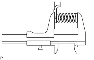
Using a vernier caliper, measure the free length of the spring together with the spring seat.
- Standard free length:
15.72 mm (0.619 in.)
If the free length is less than the standard free length, replace the 2nd brake piston spring sub-assembly.
35720
12.INSPECT FRONT PLANETARY GEAR ASSEMBLY
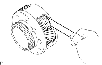
Using a feeler gauge, measure the front planetary gear pinion thrust clearance.
- Standard clearance:
0.2 to 0.6 mm (0.00788 to 0.0236 in.)
- Maximum clearance:
0.65 mm (0.0256 in.)
If the clearance is more than the maximum, replace the front planetary gear assembly.
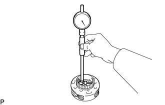
Using a cylinder gauge, measure the inside diameter of the front planetary gear bush.
- Maximum inside diameter:
57.43 mm (2.26 in.)
If the inside diameter is more than the maximum, replace the front planetary gear assembly.
35790
13.INSPECT ONE-WAY CLUTCH ASSEMBLY
Install the one-way clutch assembly to the one-way clutch inner race.
Hold the one-way clutch inner race and turn the one-way clutch assembly.
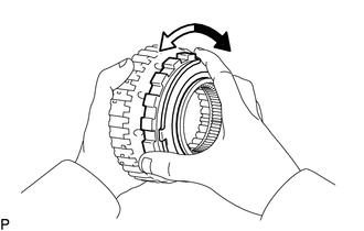
|
|
Lock |
|
|
Free |
Check that the one-way clutch assembly turns freely counterclockwise and locks clockwise.
If there is a problem with the one-way clutch, replace the one-way clutch assembly.
Remove the one-way clutch assembly from the one-way clutch inner race.
35681A
14.INSPECT NO. 1 BRAKE DISC
Check whether the sliding surfaces of the discs, plates or flange are worn or burnt. If necessary, replace them.
- NOTICE:
- ·
If the linings of the discs are peeled off or discolored, or if any part of the printed numbers is damaged, replace all discs.
·Before assembling new discs, soak them in ATF for at least 15 minutes.
35608J
15.INSPECT BRAKE PISTON RETURN SPRING SUB-ASSEMBLY
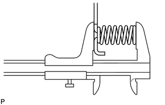
Using a vernier caliper, measure the free length of the spring together with the spring seat.
- Standard free length:
17.05 mm (0.671 in.)
If the free length is less than the standard free length, replace the brake piston return spring sub-assembly.
35682A
16.INSPECT NO. 2 BRAKE DISC
Check whether the sliding surfaces of the discs, plates or flange are worn or burnt. If necessary, replace them.
- NOTICE:
- ·
If the linings of the discs are peeled off or discolored, or if any part of the printed numbers is damaged, replace all discs.
·Before assembling new discs, soak them in ATF for at least 15 minutes.
35045
17.INSPECT NO. 2 BRAKE PISTON RETURN SPRING SUB-ASSEMBLY
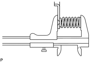
Using a vernier caliper, measure the free length of the spring together with the spring seat.
- Standard free length:
17.45 mm (0.687 in.)
If the free length is less than the standard free length, replace the No. 2 brake piston return spring sub-assembly.
35750
18.INSPECT CENTER PLANETARY GEAR ASSEMBLY
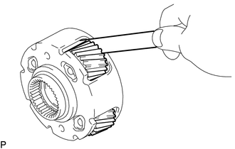
Using a feeler gauge, measure the center planetary gear pinion thrust clearance.
- Standard clearance:
0.12 to 0.68 mm (0.00473 to 0.0267 in.)
- Maximum clearance:
0.73 mm (0.0287 in.)
If the clearance is more than the maximum, replace the center planetary gear assembly.
35770C
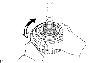
19.INSPECT NO. 3 ONE-WAY CLUTCH ASSEMBLY
|
|
Lock |
|
|
Free |
Hold the rear planetary ring gear flange and turn the one-way clutch. Check that the one-way clutch turns freely counterclockwise and locks when turned clockwise.
If there is a problem with the No. 3 one-way clutch assembly, replace the No. 3 one-way clutch assembly.
35077D
20.INSPECT REAR PLANETARY RING GEAR FLANGE SUB-ASSEMBLY
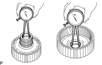
Using a dial indicator, measure the inside diameter of the rear planetary ring gear bush.
- Standard inside diameter:
32.176 to 32.201 mm (1.2668 to 1.2677 in.)
- Maximum inside diameter:
32.251 mm (1.2697 in.)
If the inside diameter is more than the maximum, replace the rear planetary ring gear flange sub-assembly.
35713
21.INSPECT INTERMEDIATE SHAFT
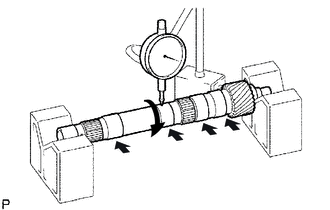
Using a dial indicator, measure the intermediate shaft runout.
- Standard runout:
0.03 mm (0.00118 in.)
- Maximum runout:
0.08 mm (0.00315 in.)
If the runout is more than the maximum, replace the intermediate shaft with a new one.
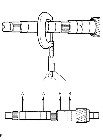
Using a micrometer, measure the diameter of the intermediate shaft at the positions shown in the diagram.
- Standard diameter:
- A:
25.962 to 25.975 mm (1.0222 to 1.0226 in.)
- B:
32.062 to 32.075 mm (1.2623 to 1.2627 in.)
If the outer diameter is outside the standard range, replace the intermediate shaft with a new one.
35684
22.INSPECT NO. 4 BRAKE DISC
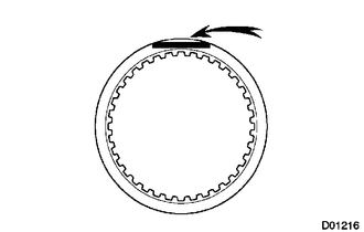
Check whether the sliding surfaces of the discs, plates or flange are worn or burnt. If necessary, replace them.
- NOTICE:
- ·
If the linings of the discs are peeled off or discolored, or if any part of the printed numbers is damaged, replace all discs.
·Before assembling new discs, soak them in ATF for at least 15 minutes.
35760
23.INSPECT REAR PLANETARY GEAR ASSEMBLY
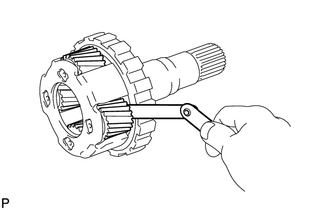
Using a feeler gauge, measure the rear planetary gear pinion thrust clearance.
- Standard clearance:
0.2 to 0.6 mm (0.00788 to 0.0236 in.)
If the clearance is more than the standard clearance, replace the rear planetary gear assembly.
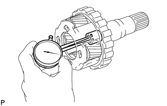
Using a dial indicator, measure the inside diameter of the rear planetary gear bush.
- Maximum inside diameter:
20.025 mm (0.788 in.)
If the inside diameter is more than the maximum, replace the rear planetary gear assembly.
35068
24.INSPECT 1ST AND REVERSE BRAKE RETURN SPRING SUB-ASSEMBLY
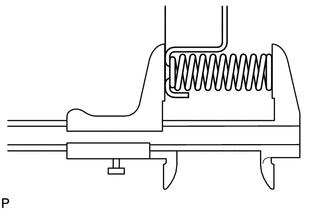
Using a vernier caliper, measure the free length of the spring together with the spring seat.
- Standard free length:
23.74 mm (0.935 in.)
If the free length is less than the standard free length, replace the 1st and reverse brake return spring sub-assembly.
25.INSPECT PACK CLEARANCE OF 1ST AND REVERSE BRAKE PISTON
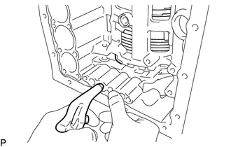
Make sure that the 1st and reverse brake piston moves smoothly when applying and releasing compressed air (392 kPa, 4.0 kgf/cm2, 57 psi).
If the 1st and reverse brake piston does not move smoothly, check the oil path of the automatic transmission case sub-assembly, 1st and reverse brake piston and O-ring.
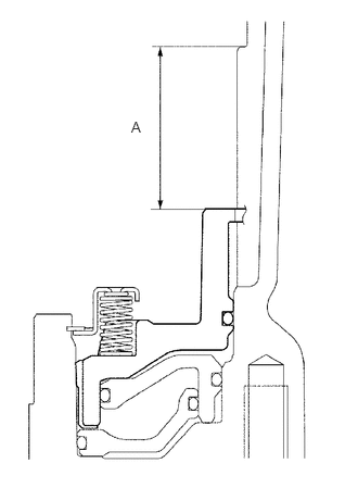
Using a vernier caliper, measure the level difference (dimension A) between the upper surface of the brake apply tube and the contact surface of the No. 4 brake flange at both ends across the 1st and reverse brake piston diameter, and calculate the average.
- NOTICE:
-
The 1st and reverse brake piston must be securely installed to the end face of the automatic transmission case sub-assembly.
- HINT:
-
Dimension A = 36.35 to 37.09 mm (1.44 to 1.46 in.)
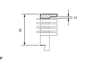
Assemble the 2 No. 4 brake flanges, 8 No. 4 brake discs and 7 No. 4 brake plates, and using a vernier caliper, measure distance B in the illustration at both ends across the diameter, and calculate the average.
Select a 1st and reverse brake flange so that the value of measured distance A minus distance B is 2.85 to 3.15 mm (0.113 to 0.124 in.).
- Flange H Thickness:
Mark Thickness 0 0 mm (0 in.) 1 0.17 mm (0.00669 in.) 3 0.31 mm (0.0122 in.) 4 0.45 mm (0.0177 in.) 5 0.59 mm (0.0232 in.) 7 0.73 mm (0.0287 in.) 8 0.87 mm (0.0343 in.) 10 1.01 mm (0.0398 in.) 11 1.15 mm (0.0453 in.) 12 1.29 mm (0.0508 in.) 14 1.43 mm (0.0563 in.)
35621V
26.INSPECT PACK CLEARANCE OF NO. 1 BRAKE PISTON
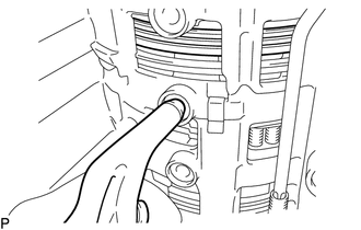
Make sure that the No. 1 brake piston moves smoothly when applying and releasing compressed air (392 kPa, 4.0 kgf/cm2, 57 psi).
If the No. 1 brake piston does not move smoothly, check the oil path of the automatic transmission case sub-assembly, No. 1 brake piston and O-rings.
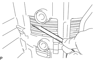
Using a feeler gauge, measure the No. 1 brake disc pack clearance between the snap flange and disc.
- Standard piston stroke:
0.42 to 0.72 mm (0.0166 to 0.0283 in.)
If the piston stroke is outside the specified range, parts may have been assembled incorrectly, so check and reassemble them again.
If the piston stroke is still outside the standard range, select another No. 1 brake flange that brings the piston stroke within the standard range.
- HINT:
-
There are 4 different thicknesses for the No. 1 brake flange that bring the piston stroke within the specified range.
- Flange Thickness:
Mark Thickness 0 2.0 mm (0.0787 in.) 1 2.2 mm (0.0866 in.) 2 2.4 mm (0.0945 in.) 3 2.6 mm (0.102 in.)
35667A
27.INSPECT PACK CLEARANCE OF DIRECT CLUTCH
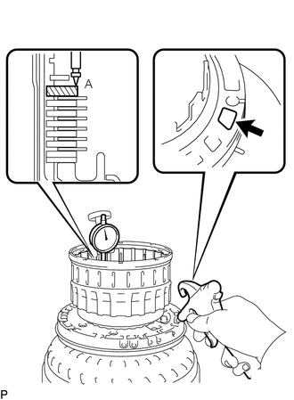
Using a dial indicator, measure the moving distance (distance A) of the direct clutch flange at both ends across a diameter while blowing air (392 kPa, 4.0 kgf/cm2, 57 psi) into the oil hole as shown in the illustration, and calculate the average.
- Standard pack clearance:
0.6 to 0.9 mm (0.0237 to 0.0354 in.)
- NOTICE:
-
Install a selective flange {t = 3.4 mm (0.134 in.)} when measuring the moving distance (shaded area in the illustration).
- HINT:
-
Flange moving distance A = 0.26 to 1.14 mm (0.0102 to 0.0448 in.)
-
Pack clearance = Flange moving distance A - 0.05 mm (0.00197 in.)
If the pack clearance is outside the standard, select and install a clutch flange that makes the pack clearance within the standard.
- HINT:
-
There are 9 types of reverse clutch flanges that can be used to adjust the pack clearance. Select one with the most appropriate thickness.
- Flange Thickness:
Mark Thickness 2 3.0 mm (0.118 in.) 3 3.1 mm (0.122 in.) 4 3.2 mm (0.126 in.) 5 3.3 mm (0.130 in.) 6 3.4 mm (0.134 in.) 7 3.5 mm (0.138 in.) 8 3.6 mm (0.142 in.) 9 3.7 mm (0.146 in.) A 3.8 mm (0.150 in.)
35049
28.INSPECT PACK CLEARANCE OF REVERSE CLUTCH
Using a dial indicator, measure the reverse clutch piston stroke (distance A) and the moving distance (distance B) of the reverse clutch flange at both ends across a diameter while blowing air (392 kPa, 4.0 kgf/cm2, 57 psi) from the oil hole as shown in the illustration, and calculate the average.
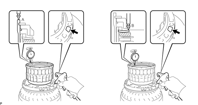
- Standard pack clearance:
0.5 to 0.8 mm (0.0197 to 0.0314 in.)
- NOTICE:
-
Install a selective flange {t = 3.3 mm (0.130 in.)} when measuring the moving distance (shaded area in the illustration).
- HINT:
-
Piston stroke A = 1.05 to 2.15 mm (0.0414 to 0.0846 in.)
-
Flange moving distance B = 0.72 to 1.08 mm (0.0284 to 0.0425 in.)
-
Pack clearance = Piston stroke A - Flange moving distance B - 0.06 mm (0.00236 in.)
If the pack clearance is outside the standard, select and install a clutch flange that makes the pack clearance within the standard.
- HINT:
-
There are 11 types of reverse clutch flanges that can be used to adjust the pack clearance. Select one with the most appropriate thickness.
- Flange Thickness:
Mark Thickness 0 2.8 mm (0.110 in.) 1 2.9 mm (0.114 in.) 2 3.0 mm (0.118 in.) 3 3.1 mm (0.122 in.) 4 3.2 mm (0.126 in.) 5 3.3 mm (0.130 in.) 6 3.4 mm (0.134 in.) 7 3.5 mm (0.138 in.) 8 3.6 mm (0.142 in.) 9 3.7 mm (0.146 in.) A 3.8 mm (0.150 in.)
29.INSPECT PACK CLEARANCE OF FORWARD CLUTCH
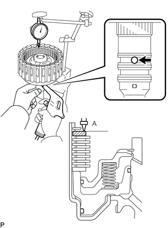
Using a dial indicator, measure the moving distance (distance A) of the coast clutch flange at both ends across a diameter while blowing air (196 kPa, 2.0 kgf/cm2, 28 psi) into the oil hole as shown in the illustration, and calculate the average.
- Standard pack clearance:
0.8 to 1.0 mm (0.0315 to 0.0394 in.)
- NOTICE:
-
When measuring the moving distance, install a standard flange (thickness: 3.4 mm (0.134 in.)) to the position of the shaded area in the illustration.
- HINT:
-
Flange moving distance A = 0.26 to 1.36 mm (0.0102 to 0.0535 in.)
-
Pack clearance = Flange moving distance A - 0.01 mm (0.000394 in.)
If the pack clearance is outside the standard, select and install a clutch flange that makes the pack clearance within the standard.
- HINT:
-
There are 11 types of forward clutch flanges that can be used to adjust the pack clearance. Select one with the most appropriate thickness.
- Flange Thickness:
Mark Thickness 0 3.0 mm (0.118 in.) 1 3.1 mm (0.122 in.) 2 3.2 mm (0.126 in.) 3 3.3 mm (0.130 in.) 4 3.4 mm (0.134 in.) 5 3.5 mm (0.138 in.) 6 3.6 mm (0.142 in.) 7 3.7 mm (0.146 in.) 8 3.8 mm (0.150 in.) 9 3.9 mm (0.154 in.) A 4.0 mm (0.157 in.)
30.INSPECT INDIVIDUAL PISTON OPERATION
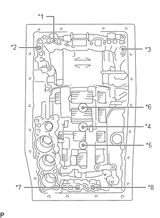
| *1 | No. 1 Clutch |
| *2 | No. 2 Clutch |
| *3 | No. 3 Clutch |
| *4 | No. 1 Brake |
| *5 | No. 2 Brake |
| *6 | No. 3 Brake |
| *7 | No. 4 Brake (In) |
| *8 | No. 4 Brake (Out) |
Check the operating sound while applying compressed air into the oil holes indicated in the illustration.
- HINT:
-
When inspecting the O/D direct clutch, check the operating sound with the C3 accumulator piston hole closed.
-
If there is no sound, disassemble and check the installation condition of the parts.