1TR-FE ENGINE MECHANICAL REAR CRANKSHAFT OIL SEAL INSTALLATION
PROCEDURE

 11381A
1.INSTALL REAR ENGINE OIL SEAL
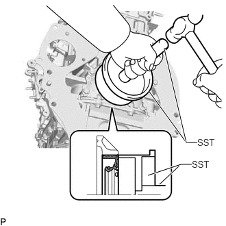
Apply a light coat of MP grease to the lip of a new rear engine oil seal.
- NOTICE:
- ·
Do not allow foreign matter to contact the lip of the rear engine oil seal.
·Do not allow MP grease to contact the dust seal.
Using SST and a hammer, tap in the rear engine oil seal until its surface is flush with the rear engine oil seal retainer edge.
- SST
- 09223-15030
09950-70010 (09951-07150)
- NOTICE:
- ·
Wipe off any extra grease from the crankshaft.
·Do not tap in the rear engine oil seal at an angle.
13405
2.INSTALL FLYWHEEL SUB-ASSEMBLY
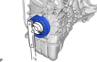
| *a | Hold |
Using SST, hold the crankshaft.
- SST
- 09213-54015 (91651-60855)
09330-00021
Clean the bolts and bolt holes.
Apply adhesive to 2 or 3 threads at the end of each of the 10 bolts.
- Adhesive:
Toyota Genuine Adhesive 1324, Three Bond 1324 or equivalent
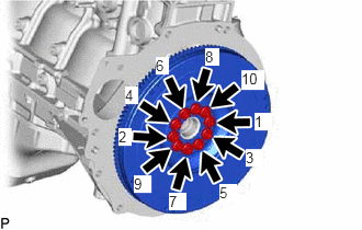
Install the flywheel sub-assembly with the 10 new bolts and uniformly tighten the bolts in several steps in the sequence shown in the illustration.
- Torque:
- 26.5 N*m (270 kgf*cm, 20 ft.*lbf)
Mark the top of the bolts with paint.
Tighten the 10 bolts 90° in the same sequence.
Check that the paint marks are now at a 90° angle to the top.
31250
3.INSTALL CLUTCH DISC ASSEMBLY
31210
4.INSTALL CLUTCH COVER ASSEMBLY
31210
5.INSPECT AND ADJUST CLUTCH COVER ASSEMBLY
33030
6.INSTALL MANUAL TRANSMISSION UNIT ASSEMBLY