2TR-FE FUEL FUEL PUMP(for Short Wheelbase) INSTALLATION
PROCEDURE

 77020A
1.INSTALL FUEL SUCTION WITH PUMP AND GAUGE TUBE ASSEMBLY
Apply a light coat of gasoline or grease to a new fuel suction tube set gasket, and install it to the fuel tank assembly.
Install the fuel suction with pump and gauge tube assembly to the fuel tank assembly.
- NOTICE:
-
Be careful not to bend the arm of the fuel sender gauge.
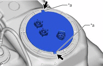
| *a | Protrusion |

|
Hole |
Align the protrusions of the fuel suction with pump and gauge tube assembly with the holes in the fuel tank assembly.
While pressing down on the fuel suction with pump and gauge tube assembly, temporarily install the fuel pump gauge retainer.
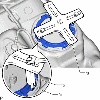
| *a | SST (Plate) |
| *b | SST (Claw) |
| *c | Insertion point |
Set the 2 claws and plate of SST on the fuel pump gauge retainer.
- SST
- 09808-14030 (09808-01030, 09808-01040)
- HINT:
-
Securely insert the ends of SST into the insertion points in the fuel pump gauge retainer.
While firmly pressing the claws of SST into the insertion points in the fuel pump gauge retainer, tighten the bolts of the claws.
Attach the handle of SST.
- SST
- 09808-14030 (09808-01010)
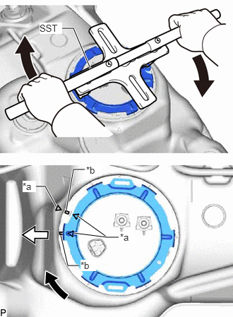
| *a | Alignment Mark |
| *b | Groove |
|
|
Turn |

|
Front of Vehicle |
Using SST, rotate the fuel pump gauge retainer so that the protrusions of the retainer are aligned with the grooves in the fuel tank assembly to install the fuel suction tube assembly with pump and gauge to the fuel tank assembly.
- NOTICE:
- ·
Do not use any tools other than SST, such as a screwdriver, etc.
·Do not use excessive force when pressing down on SST, as the fuel pump gauge retainer will place excessive force on the fuel suction tube assembly with pump and gauge and be difficult to install, and parts may be damaged.
·Be sure to keep the handle level when turning it, as SST may slip off the retainer if the handle is turned at an angle with excessive force.
·Do not use an impact wrench or turn the handle with excessive force, as parts may be damaged.
·If SST slips off the fuel pump gauge retainer, loosen the bolts and reattach SST to the fuel pump gauge retainer.
·Make sure that the fuel suction tube set gasket does not come off.
Insert the fuel tank main tube sub-assembly and fuel tank return tube into the plugs of the fuel suction with pump and gauge tube assembly and fix them in place with the 2 tube joint clips.
- NOTICE:
-
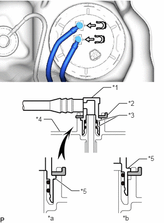 1.917,2.052 2.167,1.833 2.167,1.833 2.333,1.833 false 2.25,2.417 2.5,2.167 2.5,2.167 2.667,2.167 false 2.031,2.667 2.5,2.417 2.5,2.417 2.667,2.417 true 2.042,2.542 2.5,2.417 true 0.917,2.5 1.083,2.5 1.083,2.5 1.25,2.75 false 1.167,3.75 1.5,4 1.5,4 1.667,4 true 2.688,3.521 2.917,3.333 2.917,3.333 3.083,3.333 false 2.354,1.75 2.667,1.906 0.313,0.156 10 false *1 2.688,2.083 3,2.24 0.313,0.156 10 false *2 2.688,2.333 3,2.49 0.313,0.156 10 false *3 0.75,2.417 1.063,2.573 0.313,0.156 10 false *4 1.688,3.927 2,4.083 0.313,0.156 10 false *5 1,4.49 1.313,4.646 0.313,0.156 10 false *a 2.573,4.49 2.885,4.646 0.313,0.156 10 false *b 3.104,3.24 3.354,3.406 0.25,0.167 10 false *5
*1 Tube Joint Clip *2 Fuel Suction Plate Sub-assembly *a CORRECT *b INCORRECT *c Fuel Tube Joint *d O-Ring *e Collar
- ·
Check that there are no scratches or foreign objects on the connecting parts.
·Check that the fuel tube joints are inserted securely.
·Check that the tube joint clips are on the collars of the fuel tube joints.
·After installing the tube joint clips, check that the fuel tube joints cannot be pulled off.
·Be careful not to damage any clips.
If a clip is damaged, replace it.
77001A
2.INSTALL FUEL TANK ASSEMBLY