5L-E FUEL FUEL INJECTION PUMP INSPECTION
PROCEDURE

 22100
1.INSPECT INJECTION PUMP ASSEMBLY
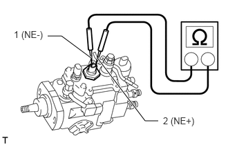
Inspect the engine speed sensor.
Measure the resistance according to the value(s) in the table below.
| Tester Connection | Condition | Specified Condition |
|---|---|---|
| 1 (NE-) - 2 (NE+) | 20°C (68°F) | 215 to 245 Ω |
If the result is not as specified, replace the injection pump assembly.
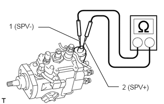
Inspect the spill control valve.
Measure the resistance according to the value(s) in the table below.
| Tester Connection | Condition | Specified Condition |
|---|---|---|
| 1 (SPV-) - 2 (SPV+) | 20°C (68°F) | 1 to 1.4 Ω |
If the result is not as specified, replace the injection pump assembly.
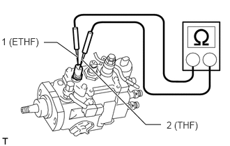
Inspect the fuel temperature sensor.
Measure the resistance according to the value(s) in the table below.
| Tester Connection | Condition | Specified Condition |
|---|---|---|
| 1 (ETHF) - 2 (THF) | 20°C (68°F) | 2.21 to 2.69 kΩ |
If the result is not as specified, replace the injection pump assembly.
23010
2.INSPECT TIMING CONTROL VALVE ASSEMBLY
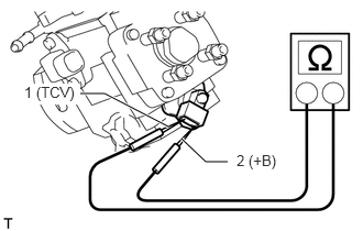
Inspect the timing control valve assembly.
Measure the resistance according to the value(s) in the table below.
| Tester Connection | Condition | Specified Condition |
|---|---|---|
| 1 (TCV) - 2 (+B) | 20°C (68°F) | 10 to 12.6 Ω |
If the result is not as specified, replace the timing control valve assembly.
Inspect the timing control valve assembly operation.
- NOTICE:
- ·
Do not apply voltage for more than 30 seconds to avoid burning out the timing control valve assembly solenoid.
·When performing this step, wait until the solenoid coils become cool enough that the solenoid can be touched by hand.
Connect the positive (+) lead of the battery to the timing control valve assembly +B terminal.
Connect the negative (-) lead of the battery to the timing control valve assembly TCV terminal.
Check that the solenoid makes a "click" sound. If the result is not as specified, replace the timing control valve assembly.
22104
3.INSPECT INJECTION PUMP DELIVERY VALVE SUB-ASSEMBLY
- NOTICE:
-
Do not touch the sliding surface of the injection pump delivery valve sub-assemblies.
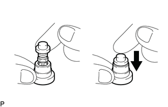
Pull up the valve and release it. Check that it sinks smoothly into the valve seat. If the operation is not as specified, replace the valve and valve seat as a set.
- HINT:
-
Before using a new valve set, wash off the rust prevention compound with diesel fuel. Then rewash with diesel fuel and perform the above test.