RM3250E
_51
Engine / Hybrid System
_038012
2GD-FTV STARTING
_0193793
RELAY
G
2GD-FTV STARTING RELAY ON-VEHICLE INSPECTION
PROCEDURE

 28300
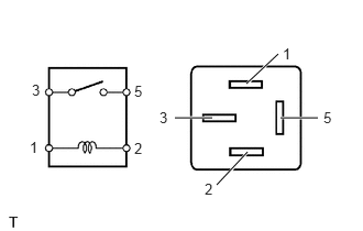
1.INSPECT NO. 1 STARTER RELAY ASSEMBLY (ST NO. 1)
a.
2.333,0.792 2.635,0.51
false
2.052,1.75 2.344,1.438
false
1.656,1.115 2.01,1.115
false
2.656,1.115 3.01,1.115
false
0.281,1.313 0.438,1.51
0.156,0.198
10
1
1.271,1.323 1.427,1.521
0.156,0.198
10
2
0.302,0.771 0.458,0.969
0.156,0.198
10
3
1.271,0.781 1.427,0.979
0.156,0.198
10
5
2.677,0.427 2.833,0.625
0.156,0.198
10
1
1.938,1.708 2.094,1.906
0.156,0.198
10
2
1.51,1.031 1.667,1.229
0.156,0.198
10
3
3.063,1.031 3.219,1.229
0.156,0.198
10
5
Measure the resistance according to the value(s) in the table below.
- Standard Resistance:
Tester Connection Condition Specified Condition 3 - 5 Battery voltage not applied to terminals 1 and 2 10 kΩ or higher Battery voltage applied to terminals 1 and 2 Below 1 Ω
If the result is not as specified, replace the No. 1 starter relay assembly.
28300F
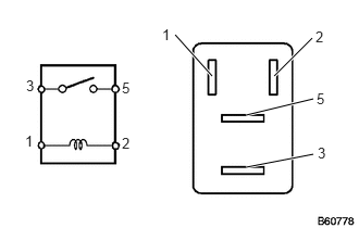
2.INSPECT NO. 2 STARTER RELAY ASSEMBLY (ST NO. 2)
a.
2.031,0.729 1.677,0.333
true
2.625,0.729 2.99,0.365
true
2.354,1.104 3,0.948
true
2.354,1.604 3,1.479
true
1.552,0.25 1.698,0.417
0.146,0.167
10
false
1
3.021,0.271 3.167,0.427
0.146,0.156
10
false
2
3.031,0.865 3.219,1.021
0.188,0.156
10
false
5
3.042,1.385 3.167,1.542
0.125,0.156
10
false
3
1.167,0.76 1.333,0.938
0.167,0.177
10
false
5
1.167,1.292 1.313,1.458
0.146,0.167
10
false
2
0.25,0.74 0.396,0.906
0.146,0.167
10
false
3
0.24,1.271 0.354,1.438
0.115,0.167
10
false
1
Measure the resistance according to the value(s) in the table below.
- Standard Resistance:
Tester Connection Condition Specified Condition 3 - 5 Battery voltage not applied to terminals 1 and 2 10 kΩ or higher Battery voltage applied to terminals 1 and 2 Below 1 Ω
If the result is not as specified, replace the starter relay.
28610
3.INSPECT GLOW RELAY (GLOW)
a.
2.333,0.792 2.635,0.51
false
2.052,1.75 2.344,1.438
false
1.656,1.115 2.01,1.115
false
2.656,1.115 3.01,1.115
false
0.281,1.313 0.438,1.51
0.156,0.198
10
1
1.271,1.323 1.427,1.521
0.156,0.198
10
2
0.302,0.771 0.458,0.969
0.156,0.198
10
3
1.271,0.781 1.427,0.979
0.156,0.198
10
5
2.677,0.427 2.833,0.625
0.156,0.198
10
1
1.938,1.708 2.094,1.906
0.156,0.198
10
2
1.51,1.031 1.667,1.229
0.156,0.198
10
3
3.063,1.031 3.219,1.229
0.156,0.198
10
5
Measure the resistance according to the value(s) in the table below.
- Standard Resistance:
Tester Connection Condition Specified Condition 3 - 5 Battery voltage not applied to terminals 1 and 2 10 kΩ or higher Battery voltage applied to terminals 1 and 2 Below 1 Ω
If the result is not as specified, replace the glow relay.