DOOR LOCK UNLOCK WARNING SWITCH REMOVAL
CAUTION / NOTICE / HINT
The necessary procedures (adjustment, calibration, initialization or registration) that must be performed after parts are removed, installed or replaced during the unlock warning switch assembly removal/installation are shown below.
| Replacement Part or Procedure | Necessary Procedures | Effects / Inoperative when not Performed | Link |
|---|---|---|---|
| Disconnect cable from negative battery terminal | Drive the vehicle until stop and start control is permitted (approximately 5 to 60 minutes) | Stop and start system | ( ) |
| Memorize steering angle neutral point | Pre-crash safety system | ()
|
- HINT:
- ·
Use the same procedure for RHD and LHD vehicles.
·The procedures listed below are for LHD vehicles.
PROCEDURE

 1. PRECAUTION
- NOTICE:
-
After turning the ignition switch off, waiting time may be required before disconnecting the cable from the negative (-) battery terminal. Therefore, make sure to read the disconnecting the cable from the negative (-) battery terminal notice before proceeding with work.
-
Click hereGeneral>INTRODUCTION>REPAIR INSTRUCTION>PRECAUTION
2.DISCONNECT CABLE FROM NEGATIVE BATTERY TERMINAL
- NOTICE:
-
When disconnecting the cable, some systems need to be initialized after the cable is reconnected.
-
Click hereGeneral>INTRODUCTION>REPAIR INSTRUCTION>INITIALIZATION
45287
3.REMOVE LOWER STEERING COLUMN COVER
45286B
4.REMOVE UPPER STEERING COLUMN COVER
89782
5.REMOVE TRANSPONDER KEY COIL (w/ Engine Immobiliser System)
69057A
6.REMOVE IGNITION SWITCH LOCK CYLINDER ASSEMBLY
84052
7.REMOVE UNLOCK WARNING SWITCH ASSEMBLY
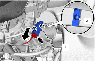
| *a | Center Part |

|
Remove in this Direction |
Detach the connector.
Push up the center part of the unlock warning switch assembly, detach the claw and remove the unlock warning switch assembly.
- HINT:
-
Slide the unlock warning switch assembly in the direction indicated by the arrow in the illustration to remove it.