CRUISE CONTROL CRUISE CONTROL SYSTEM TERMINALS OF ECU
CHECK ECM (for 1GD-FTV)
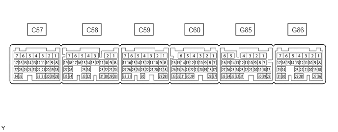
- HINT:
-
Each ECM terminal's standard voltage is shown in the table below.
-
In the table, first follow the information under "Condition". Look under "Terminal No. (Symbol)" for the terminals to be inspected. The standard voltage between the terminals is shown under "Specified Condition".
-
Use the illustration above as a reference for the ECM terminals.
| Terminal No. (Symbol) | Wiring Color | Terminal Description | Condition | Specified Condition |
|---|---|---|---|---|
| C57-14 (D) - C60-1 (E1) | GR - W-B | D shift position signal | Ignition switch ON and shift lever in D, S, "+" or "-" | 11 to 14 V |
| Ignition switch ON and shift lever not in D, S, "+" or "-" | Below 1 V | |||
| C60-1 (E1) - Body ground | W-B - Body ground | Ground | Always | Below 1 Ω |
| G85-13 (S) - C60-1 (E1) | L - W-B | S shift position switch signal | Ignition switch ON and shift lever in S, "+" or "-" | 11 to 14 V |
| Ignition switch ON and shift lever not in S, "+" or "-" | Below 1 V | |||
| G85-20 (SFTD) - C60-1 (E1) | G - W-B | Down-shift switch signal | Ignition switch ON and shift lever in S | 11 to 14 V |
| Ignition switch ON and shift lever in "-" (down-shift) | Below 1 V | |||
| G85-21 (SFTU) - C60-1 (E1) | W - W-B | Up-shift switch signal | Ignition switch ON and shift lever in S | 11 to 14 V |
| Ignition switch ON and shift lever in "+" (up-shift) | Below 1 V | |||
| G86-1 (BATT) - C60-1 (E1) | Y - W-B | Battery (for measuring battery voltage and for ECM memory) | Always | 11 to 14 V |
| G86-12 (ST1-) - C60-1 (E1) | GR - W-B | Stop light switch assembly signal
(opposite to voltage at STP terminal) |
Ignition switch ON,
brake pedal depressed |
0 to 1.5 V |
| Ignition switch ON,
brake pedal released |
7.5 to 14 V | |||
| G86-13 (STP) - C60-1 (E1) | L - W-B | Stop light switch assembly signal | Brake pedal depressed | 7.5 to 14 V |
| Brake pedal released | 0 to 1.5 V | |||
| G86-26 (CCS) - C60-1 (E1) | G - W-B | Cruise control switch circuit | Cruise control main switch off | 1 MΩ or higher |
| Cruise control main switch on | Below 2.5 Ω | |||
| +RES switch on | 235 to 245 Ω | |||
| -SET switch on | 617 to 643 Ω | |||
| CANCEL switch on | 1509 to 1571 Ω |
CHECK ECM (for 1KD-FTV)
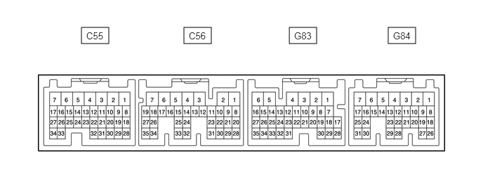
- HINT:
-
Each ECM terminal's standard voltage is shown in the table below.
-
In the table, first follow the information under "Condition". Look under "Terminal No. (Symbol)" for the terminals to be inspected. The standard voltage between the terminals is shown under "Specified Condition".
-
Use the illustration above as a reference for the ECM terminals.
| Terminal No. (Symbol) | Wiring Color | Terminal Description | Condition | Specified Condition |
|---|---|---|---|---|
| C56-7 (E1) - Body ground | W-B - Body ground | Ground | Always | Below 1 Ω |
| G83-2 (BATT) - C56-7 (E1) | Y - W-B | Battery (for measuring the battery voltage and for the ECM memory) | Always | 11 to 14 V |
| G83-14 (ST1-) - C56-7 (E1) | GR - W-B | Stop light switch assembly signal
(opposite to voltage at STP terminal) |
Ignition switch ON,
brake pedal depressed |
0 to 1.5 V |
| Ignition switch ON,
brake pedal released |
7.5 to 14 V | |||
| G83-15 (STP) - C56-7 (E1) | L - W-B | Stop light switch assembly signal | Brake pedal depressed | 7.5 to 14 V |
| Brake pedal released | 0 to 1.5 V | |||
| G84-21 (CCS) - C56-7 (E1) | G - W-B | Cruise control switch circuit | Cruise control main switch off | 1 MΩ or higher |
| Cruise control main switch on | Below 2.5 Ω | |||
| +RES switch on | 235 to 245 Ω | |||
| -SET switch on | 617 to 643 Ω | |||
| CANCEL switch on | 1509 to 1571 Ω |
CHECK TCM (for 1KD-FTV)
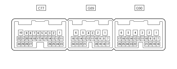
- HINT:
-
Each TCM terminal's standard voltage is shown in the table below.
-
In the table, first follow the information under "Condition". Look under "Terminal No. (Symbol)" for the terminals to be inspected. The standard voltage between the terminals is shown under "Specified Condition".
-
Use the illustration above as a reference for the TCM terminals.
| Terminal No. (Symbol) | Wiring Color | Terminal Description | Condition | Specified Condition |
|---|---|---|---|---|
| G89-8 (D) - C77-1 (E1) | P - W-B | D shift position switch signal | Ignition switch ON and shift lever in D, S, "+" or "-" | 11 to 14 V |
| Ignition switch ON and shift lever not in S, "+" or "-" | Below 1 V | |||
| C77-1 (E1) - Body ground | W-B - Body ground | Ground | Always | Below 1 Ω |
| G90-15 (S) - C77-1 (E1) | L - W-B | S shift position switch signal | Ignition switch ON and shift lever in S, "+" or "-" | 11 to 14 V |
| Ignition switch ON and shift lever not in S, "+" or "-" | Below 1 V | |||
| G90-22 (SFTU) - C77-1 (E1) | W - W-B | Up-shift position switch signal | Ignition switch ON and shift lever in S | 11 to 14 V |
| Ignition switch ON and shift lever in "+" position (up-shift) | Below 1 V | |||
| G90-23 (SFTD) - C77-1 (E1) | G - W-B | Down-shift position switch signal | Ignition switch ON and shift lever in S | 11 to 14 V |
| Ignition switch ON and shift lever in "-" (down-shift) | Below 1 V |