RM33J0E
_56
Audio / Visual / Telematics
_038485
AUDIO / VIDEO
_0193314
AUDIO AND VISUAL SYSTEM(for Radio Receiver Type)
U
AUDIO / VIDEO AUDIO AND VISUAL SYSTEM(for Radio Receiver Type) TERMINALS OF ECU
RADIO RECEIVER ASSEMBLY
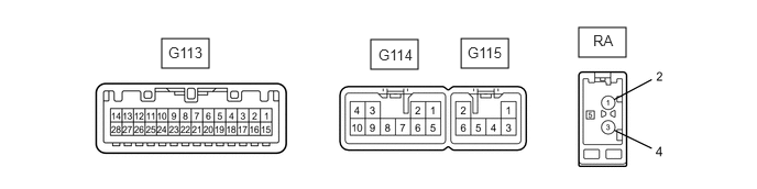
1.531,0.365 1.979,0.646
0.448,0.281
3.51,0.375 3.958,0.656
0.448,0.281
4.365,0.365 4.813,0.646
0.448,0.281
5.479,0.26 5.927,0.542
0.448,0.281
1.594,0.417 2.052,0.615
0.458,0.198
10
false
G113
5.615,0.302 6.073,0.5
0.458,0.198
10
false
RA
3.583,0.438 4.042,0.635
0.458,0.198
10
false
G114
4.427,0.417 4.885,0.615
0.458,0.198
10
false
G115
| Terminal No. (Symbol) | Wiring Color | Terminal Description | Condition | Specified Condition |
|---|---|---|---|---|
|
#: There is no wire color information *1: for 4 or 6 Speakers *2: for TFT Display Type *3: except TFT Display Type |
||||
| G114-1 (FR+) - G114-5 (FR-) | LG - L | Sound signal (Right) | Audio system playing | A waveform synchronized with sound signals is output |
| G114-2 (FL+) - G114-6 (FL-) | P - V | Sound signal (Left) | Audio system playing | A waveform synchronized with sound signals is output |
| G114-3 (ACC1) - G114-7 (GND1) | GR - BR | Power source (ACC) | Ignition switch ACC | 11 to 14 V |
| Ignition switch off | Below 1 V | |||
| G114-4 (+B1) - G114-7 (GND1) | SB - BR | Power source (+B) | Always | 11 to 14 V |
| G114-7 (GND1) - Body ground | BR - Body ground | Ground | Always | Below 1 V |
| G114-10 (ILL+) - G114-7 (GND1) | G - BR | Illumination signal | Headlight dimmer switch in tail or head position | 11 to 14 V |
| Headlight dimmer switch off | Below 1 V | |||
| G115-1 (RR+) - G115-3 (RR-)*1 | R - W | Sound signal (Right) | Audio system playing | A waveform synchronized with sound signals is output |
| G115-2 (RL+) - G115-6 (RL-)*1 | B - Y | Sound signal (Left) | Audio system playing | A waveform synchronized with sound signals is output |
| G115-5 (ILL-) - G114-7 (GND1)*2 | W - BR | Illumination signal | Headlight dimmer switch off | Below 1 V |
| Headlight dimmer switch in tail or head position | Pulse generation | |||
| G115-5 (ILL-) - G114-7 (GND1)*3 | W - BR | Illumination signal | Always | Below 1 V |
| G113-3 (ADIM) - G114-7 (GND1) | W - BR | Dimming signal | Ignition switch ON, automatic light control sensor covered by hand, and light control switch in tail or head position | 9 V or higher |
| G113-4 (MACC) - G114-7 (GND1) | B - BR | Telephone microphone assembly power supply | Ignition switch ACC | 4 to 6 V |
| Ignition switch off | Below 1 V | |||
| G113-5 (MIN+) - G114-7 (GND1) | W - BR | Telephone microphone assembly voice signal | "Bluetooth" hands-free function on | A waveform synchronized with sound is output |
| G113-6 (SNS2) - G114-7 (GND1) | W-B - BR | Ground | Always | Below 1 V |
| G113-17 (SPD) - G114-7 (GND1) | V - BR | Vehicle speed signal | Wheel being rotated | Pulse generation |
| G113-18 (SGND) - Body ground | Shielded - Body ground | Shielded ground | Always | Below 1 V |
| G113-19 (MIN-) - G114-7 (GND1) | R - BR | Telephone microphone assembly voice signal | "Bluetooth" hands-free function on | A waveform synchronized with sound is output |
| G113-21 (SW1) - G113-23 (SWG) | Y - V | Steering pad switch signal | Steering pad switch not operated | 2.7 to 3.3 V |
| Seek+ switch pushed | Below 0.5 V | |||
| Seek- switch pushed | 0.5 to 0.9 V | |||
| Volume+ switch pushed | 1.0 to 1.7 V | |||
| Volume- switch pushed | 1.8 to 2.6 V | |||
| G113-22 (SW2) - G113-23 (SWG) | G - V | Steering pad switch signal | Steering pad switch not operated | 2.7 to 3.3 V |
| MODE switch pushed | Below 0.5 V | |||
| On hook switch pushed | 0.5 to 0.9 V | |||
| Off hook switch pushed | 1.0 to 1.7 V | |||
| G113-23 (SWG) - G114-7 (GND1) | V - BR | Steering pad switch ground | Always | Below 1 V |
| RA-5 (ANT+) - G114-7 (GND1) | # - BR | Power source of antenna | Ignition switch ACC, radio switch on and FM or AM selected | 11 to 14 V |