DOOR / HATCH TAIL GATE REASSEMBLY
CAUTION / NOTICE / HINT
- HINT:
-
A bolt without a torque specification is shown in the standard bolt chart.
-
Click hereGeneral>SPECIFICATIONS>STANDARD BOLT>SPECIFIED TORQUE FOR STANDARD BOLTS
PROCEDURE

 65778
1.INSTALL TAIL GATE STAY STOPPER
- HINT:
-
Use the same procedure for both tail gate stay stoppers.
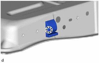
Attach the claw to install the tail gate stay stopper.
66120F
2.INSTALL TAIL GATE HINGE ASSEMBLY LH
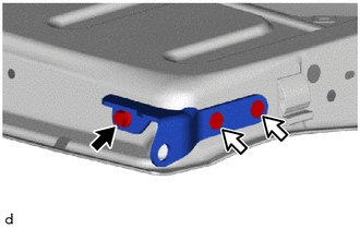

|
Bolt |

|
"TORX" Bolt |
Install the tail gate hinge assembly LH with the bolt.
- Torque:
- 25 N*m (255 kgf*cm, 18 ft.*lbf)
Using a T40 "TORX" socket wrench, install the 2 "TORX" bolts.
- Torque:
- 28 N*m (286 kgf*cm, 21 ft.*lbf)
66110F
3.INSTALL TAIL GATE HINGE ASSEMBLY RH
- HINT:
-
Use the same procedure described for the LH side.
66170
4.INSTALL REAR BODY TAIL GATE LATCH ASSEMBLY (for J Deck)
- HINT:
-
Use the same procedure for both rear body tail gate latch assemblies.
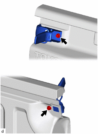
Install the rear body tail gate latch assembly with the 2 bolts.
65738A
5.INSTALL NO. 1 TAIL GATE LOCK HINGE STOPPER (for A Deck)
- HINT:
-
Use the same procedure for both No. 1 tail gate lock hinge stoppers.
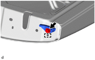
Attach the guide to install the No. 1 tail gate lock hinge stopper with the bolt.
65790A
6.INSTALL TAIL GATE LOCK ASSEMBLY LH (for A Deck)
Apply MP grease to the sliding area of the tail gate lock assembly LH.
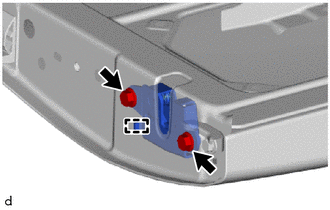
Attach the guide to install the tail gate lock assembly with the 2 bolts.
65780A
7.INSTALL TAIL GATE LOCK ASSEMBLY RH (for A Deck)
- HINT:
-
Use the same procedure described for the LH side.
69090B
8.INSTALL TAIL GATE HANDLE ASSEMBLY (for A Deck)
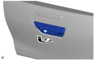

|
Install in this Direction |
Temporarily install the tail gate handle assembly as shown in the illustration.
Install the tail gate handle assembly with the 4 bolts.
- Torque:
- 5.0 N*m (51 kgf*cm, 44 in.*lbf)
65797A
9.INSTALL TAIL GATE LOCK CONTROL LINK LH (for A Deck)
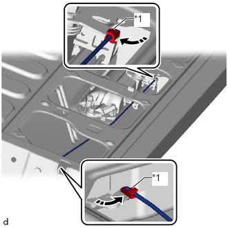
| *1 | Control Link Snap |
|
|
Install in this Direction |
Install the tail gate lock control link LH.
Rotate the control link snaps in the directions indicated by the arrows in the illustration and attach the control link snaps to the tail gate lock control link LH.
65797B
10.INSTALL TAIL GATE LOCK CONTROL LINK RH (for A Deck)
- HINT:
-
Use the same procedure described for the LH side.
86790D
11.INSTALL REAR TELEVISION CAMERA ASSEMBLY (w/ Rear View Monitor System)
81570
12.INSTALL CENTER STOP LIGHT ASSEMBLY
13.INSTALL SCREW GROMMET
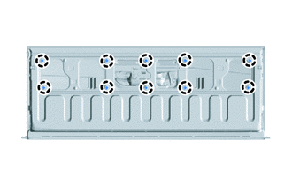
for A Deck:
Attach the claw to install the 10 new screw grommets.
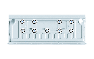
for J Deck:
Attach the claw to install the 9 new screw grommets.
65759
14.INSTALL TAIL GATE SERVICE HOLE COVER
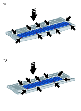
| *A | for A Deck |
| *B | for J Deck |
|
|
Install in this Direction |
for A Deck:
Install the tail gate service hole cover with the 10 screws.
for J Deck:
Install the tail gate service hole cover with the 9 screws.