RM33J0E
_58
Vehicle Interior
_038504
HEATING / AIR CONDITIONING
_0193640
AIR CONDITIONING SYSTEM(for Manual Air Conditioning System)
D
HEATING / AIR CONDITIONING AIR CONDITIONING SYSTEM(for Manual Air Conditioning System) SYSTEM DESCRIPTION
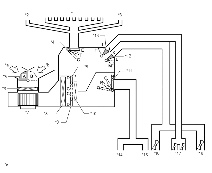
MODE POSITION AND DAMPER OPERATION
1.875,1.417 2.042,1.417
2.042,1.417 2.292,1.667
true
3.76,1.896 4.177,1.896
true
3.375,1.208 3.542,1.208
3.542,1.208 3.594,1.708
true
0.25,2.99 0.667,2.99
true
0.271,2.583 0.688,2.583
true
1.719,3.844 1.885,3.844
1.885,3.844 2.135,3.51
true
2.073,4.125 2.24,4.125
2.24,4.125 2.406,3.542
true
3.01,3.833 2.844,3.833
2.844,3.833 2.542,3.333
true
4.219,2.396 4.052,2.396
4.052,2.396 3.802,2.729
true
2.802,2.26 2.635,2.26
2.635,2.26 2.417,2.604
true
2.406,0.354 2.719,0.552
0.313,0.198
10
false
*1
0.844,0.417 1.156,0.615
0.313,0.198
10
false
*2
3.99,0.417 4.302,0.615
0.313,0.198
10
false
*3
1.708,1.333 2.021,1.531
0.313,0.198
10
false
*4
3.135,1.115 3.448,1.313
0.313,0.198
10
false
*13
4.229,1.802 4.542,2
0.313,0.198
10
false
*12
0.073,2.906 0.385,3.104
0.313,0.198
10
false
*6
0.104,2.5 0.417,2.698
0.313,0.198
10
false
*5
0.167,2.104 0.479,2.302
0.313,0.198
10
false
*a
1.542,2.104 1.854,2.302
0.313,0.198
10
false
*b
0.854,3.708 1.167,3.906
0.313,0.198
10
false
*7
1.479,3.75 2.031,3.969
0.552,0.219
10
false
*8
3.052,3.75 3.719,3.979
0.667,0.229
10
false
*10
4.271,2.302 4.99,2.552
0.719,0.25
10
false
*11
3.938,5.135 4.583,5.313
0.646,0.177
10
false
*14
4.792,5.135 5.323,5.333
0.531,0.198
10
false
*15
5.188,5.083 5.5,5.281
0.313,0.198
10
false
*16
5.917,5.083 6.229,5.281
0.313,0.198
10
false
*17
6.667,5.083 6.979,5.281
0.313,0.198
10
false
*18
0.156,5.469 0.469,5.667
0.313,0.198
10
false
*c
2.854,2.167 3.375,2.385
0.521,0.219
10
false
*9
1.865,4.031 2.385,4.25
0.521,0.219
10
false
*9
| Damper | Operation Position | Damper Position | Operation |
|---|---|---|---|
| Air Inlet Control Damper | FRESH | A | Brings in fresh air. |
| RECIRC | B | Recirculates internal air. | |
| Air Mix Control Damper | HI - LO | C - D | Varies the mixture ratio of cool air and hot air in order to regulate the temperature continuously from HI to LO. |
| Mode Control Damper | FACE | E, H, M, N | Air blows out of the center register and side register. |
| BI-LEVEL | E, I, L, P | Air blows out of the center register, side register and footwell register. | |
| FOOT | F, J, K, Q | Air blows out of the footwell register duct. A small amount of air also blows out from the side register, front defroster and side defroster. | |
| FOOT/DEF | F, J, K, P | Defrosts the windshield through the front defroster and side defroster. At the same time, air is blown out from the footwell register. A small amount of air also blows out from the side register. | |
| DEF* | G, J, K, N | Defrosts the windshield through the front defroster and side defroster. A small amount of air also blows out from the side register. |
AIR OUTLETS AND AIR FLOW VOLUME
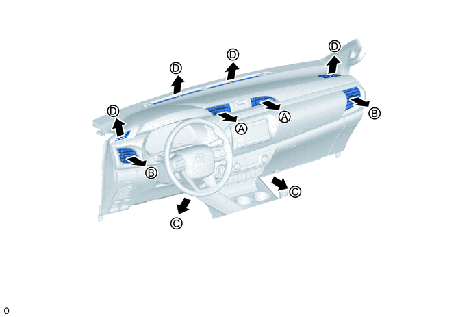
| Indication | Mode | Center Register | Side Register | Footwell Duct | Front Defroster, Side Defroster |
|---|---|---|---|---|---|
| A | B | C | D | ||

|
FACE | 
|
|
- | - |

|
BI-LEVEL | 
|
|
|
- |

|
FOOT | - | 
|
|
|

|
FOOT/DEF | - |
|
|
|

|
DEF | - |
|
- |
|
- HINT:
-
The circle size (○) is proportional to the amount of air flow.