1GD-FTV ENGINE CONTROL CRANKSHAFT POSITION SENSOR REMOVAL
CAUTION / NOTICE / HINT
The necessary procedures (adjustment, calibration, initialization, or registration) that must be performed after parts are removed, installed, or replaced during the crankshaft position sensor removal/installation are shown below.
| Replacement Part or Procedure | Necessary Procedures | Effects/Inoperative when not Performed | Link |
|---|---|---|---|
| Replacement of ECM | ·
Learning values save ·
Learning values write ·
Vehicle Identification Number (VIN) registration |
·
Engine starting ·
DTC P0630 is output |
( ) w/ DPF:( )
|
| Code registration (Immobiliser system) | Engine start function | See the Service Bulletin for the registration method. | |
| Replacement of engine assembly | ·
Input Injector Compensation Code ·
Pilot Quantity Learning |
Engine starting | ()
w/ DPF:( )
|
| Clear Crank Time Compensation Data | Engine starting | ()
w/ DPF:( )
|
|
| Replacement of automatic transmission assembly | Reset memory | ·
Large shift shock ·
Engine overruns |
()
|
| Replacement of automatic transmission fluid | ATF thermal degradation estimate reset | The value of the Data List item "ATF Thermal Degradation Estimate" is not estimated correctly | |
| Front wheel alignment adjustment | ·
Clearing zero point calibration data ·
Yaw rate and acceleration sensor zero point calibration |
VSC malfunctioning | ()
|
PROCEDURE

 1.REMOVE AUTOMATIC TRANSMISSION ASSEMBLY (for Automatic Transmission)
2.REMOVE MANUAL TRANSMISSION ASSEMBLY (for Manual Transmission)
31210
3.REMOVE CLUTCH COVER ASSEMBLY (for Manual Transmission)
31250
4.REMOVE CLUTCH DISC ASSEMBLY (for Manual Transmission)
13405
5.REMOVE FLYWHEEL SUB-ASSEMBLY
11355
6.REMOVE REAR END PLATE
12581A
7.REMOVE NO. 1 CYLINDER BLOCK INSULATOR
12585
8.REMOVE NO. 5 CYLINDER BLOCK INSULATOR
27148C
9.REMOVE CONNECTING WIRE
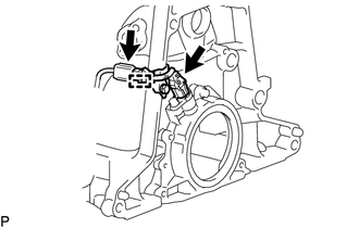
Disconnect the 2 connectors and clamp and remove the connecting wire.
10.REMOVE CRANKSHAFT POSITION SENSOR HARNESS BRACKET
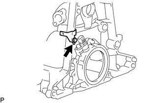
Remove the bolt and crankshaft position sensor harness bracket from the cylinder block sub-assembly.
11401Q
11.REMOVE CRANKSHAFT POSITION SENSOR
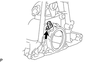
Remove the bolt and crankshaft position sensor from the rear oil seal retainer.