RM33J0E
_52
Drivetrain
_038470
VF2CM TRANSFER / 4WD / AWD
_0197772
TOUCH SELECT 2-4 AND HIGH-LOW SYSTEM
U
VF2CM TRANSFER / 4WD / AWD TOUCH SELECT 2-4 AND HIGH-LOW SYSTEM TERMINALS OF ECU
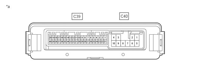
CHECK 4 WHEEL DRIVE CONTROL ECU
2.552,0.469 2.927,0.698
0.375,0.229
4.24,0.448 4.563,0.698
0.323,0.25
2.604,0.5 3.063,0.698
0.458,0.198
10
false
C39
4.281,0.49 4.552,0.656
0.271,0.167
10
false
C40
0.219,0.146 0.469,0.333
0.25,0.188
10
false
*a
| *a | Component with harness connected
(4 Wheel Drive Control ECU) |
- | - |
a.
Measure the resistance and voltage according to the value(s) in the table below.
| Terminal No. (Symbol) | Wiring Color | Terminal Description | Condition | Specified Condition |
|---|---|---|---|---|
| C39-1 (4WD) - C40-10 (GND) | W - W-B | 4WD detection switch signal input | Ignition switch ON
Transfer position 2WD |
10 to 14 V |
| Ignition switch ON
Transfer position 4WD |
Below 1.5 V | |||
| C39-2 (ADD) - C40-10 (GND)*3 | W - W-B | A.D.D. position switch input | Ignition switch ON
Transfer position 2WD (A.D.D. actuator Free) |
10 to 14 V |
| Ignition switch ON
Transfer position 4WD (A.D.D. actuator Lock) |
Below 1.5 V | |||
| C39-3 (4WDL) - C40-10 (GND) | Y - W-B | L4 detection switch signal input | Ignition switch ON
Transfer position not in L4 |
10 to 14 V |
| Ignition switch ON
Transfer position L4 |
Below 1.5 V | |||
| C39-5 (DT) - C39-25 (DGND) | G - B | Oil temperature sensor signal input | Ignition switch ON | 0.9 to 4.9 V |
| C39-7 (DL2) - C40-10 (GND)*3 | B - W-B | A.D.D. actuator limit switch input | Ignition switch ON
Transfer position 2WD (A.D.D. actuator Free) |
10 to 14 V |
| Ignition switch ON
Transfer position 4WD (A.D.D. actuator Lock) |
Below 1.5 V | |||
| C39-8 (DL1) - C40-10 (GND)*3 | G - W-B | A.D.D. actuator limit switch input | Ignition switch ON
Transfer position 2WD (A.D.D. actuator Free) |
Below 1.5 V |
| Ignition switch ON
Transfer position 4WD (A.D.D. actuator Lock) |
10 to 14 V | |||
| C39-9 (TL3) - C40-10 (GND) | W - W-B | Transfer shift actuator limit switch input | Ignition switch ON
TL3 terminal limit switch off (transfer H2 or L4) |
10 to 14 V |
| Ignition switch ON
TL3 terminal limit switch on (transfer H4) |
Below 1.5 V | |||
| C39-10 (TL2) - C40-10 (GND) | G - W-B | Transfer shift actuator limit switch input | Ignition switch ON
TL2 terminal limit switch off (transfer H2 or H4) |
10 to 14 V |
| Ignition switch ON
TL2 terminal limit switch on (transfer L4) |
Below 1.5 V | |||
| C39-11 (TL1) - C40-10 (GND) | L - W-B | Transfer shift actuator limit switch input | Ignition switch ON
TL1 terminal limit switch off (transfer H4 or L4) |
10 to 14 V |
| Ignition switch ON
TL1 terminal limit switch on (transfer H2) |
Below 1.5 V | |||
| C39-13 (LO) - C40-10 (GND) | B - W-B | Transfer position switch input | Ignition switch ON
Transfer position switch H2 |
10 to 14 V |
| Ignition switch ON
Transfer position switch H4 |
Below 1.5 V | |||
| Ignition switch ON
Transfer position switch L4 |
Below 1.5 V | |||
| C39-14 (2-4) - C40-10 (GND) | L - W-B | Transfer position switch input | Ignition switch ON
Transfer position switch H2 |
Below 1.5 V |
| Ignition switch ON
Transfer position switch H4 |
Below 1.5 V | |||
| Ignition switch ON
Transfer position switch L4 |
10 to 14 V | |||
| C39-18 (MTN) - C40-10 (GND)*2 | L - W-B | Clutch start switch input | Ignition switch ON
Clutch pedal released |
10 to 14 V |
| Ignition switch ON
Clutch pedal depressed |
Below 2 V | |||
| C39-20 (CANH) - C39-40 (CANL) | R - W | HIGH-level CAN bus wire - LOW-level CAN bus wire | Ignition switch off
Cable disconnected from negative (-) battery terminal |
54 to 69 Ω |
| C39-21 (+B) - C40-10 (GND) | L - W-B | ECU power supply | Always | 11 to 14 V |
| C40-2 (DM1) - C40-10 (GND)*3 | W - W-B | A. D. D. shift motor output | Ignition switch ON
Transfer position switch H4 to H2 (during A.D.D. actuator Lock to Free operation) |
Pulse generation
(see waveform 1) |
| C40-4 (IG) - C40-10 (GND) | G - W-B | ECU and actuator power supply | Ignition switch ON | 11 to 14 V |
| C40-6 (DM2) - C40-10 (GND)*3 | R - W-B | A. D. D. shift motor output | Ignition switch ON
Transfer position switch H2 to H4 (during A.D.D. actuator Free to Lock operation) |
Pulse generation
(see waveform 1) |
| C40-7 (TM2) - C40-10 (GND) | Y - W-B | Transfer shift motor output | Ignition switch ON
Shift lever in N*1 Shift lever in neutral*2 Transfer position switch turned from H2 to H4 (switching from H2 to H4) Transfer position switch turned from H4 to L4 (switching from H4 to L4) |
Pulse generation
(see waveform 2) |
| C40-8 (TM1) - C40-10 (GND) | B - W-B | Transfer shift motor output | Ignition switch ON
Shift lever in N*1 Shift lever in neutral*2 Transfer position switch turned from L4 to H4 (switching from L4 to H4) |
Pulse generation
(see waveform 2) |
| C40-10 (GND) - Body ground | W-B - Body ground | Ground | Always | Below 1 Ω |
*1: for Automatic Transmission
*2: for Manual Transmission
*3: w/ A.D.D. Actuator
b.
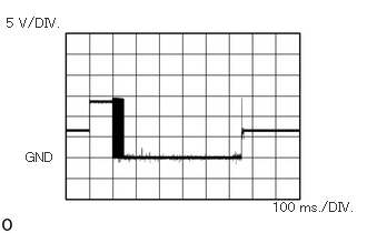
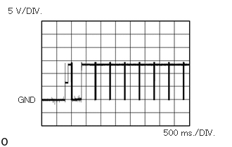
Waveform 1 (w/ A.D.D. Actuator)
i.
0.24,1.406 0.552,1.583
0.313,0.177
10
false
GND
0.063,0.146 0.656,0.313
0.594,0.167
10
false
5 V/DIV.
2.552,1.875 3.385,2.073
0.833,0.198
10
false
100 ms./DIV.
When a gear is engaged and switching is performed
| Item | Content |
|---|---|
| Tester Connection | C40-2 (DM1) - C40-10 (GND) |
| Tool Setting | 5 V/DIV., 100 ms./DIV. |
| Condition | Ignition switch ON
Transfer position switch H4 to H2 (during A.D.D. actuator Lock to Free operation) |
| Item | Content |
|---|---|
| Tester Connection | C40-6 (DM2) - C40-10 (GND) |
| Tool Setting | 5 V/DIV., 100 ms./DIV. |
| Condition | Ignition switch ON
Transfer position switch H2 to H4 (during A.D.D. actuator Free to Lock operation) |
ii.
0.271,1.417 0.729,1.615
0.458,0.198
10
false
GND
0.125,0.094 0.698,0.26
0.573,0.167
10
false
5 V/DIV.
2.427,1.906 3.333,2.094
0.906,0.188
10
false
500 ms./DIV.
When a gear is not engaged and switching is not performed
| Item | Content |
|---|---|
| Tester Connection | C40-2 (DM1) - C40-10 (GND) |
| Tool Setting | 5 V/DIV., 500 ms./DIV. |
| Condition | Ignition switch ON
Transfer position switch H4 to H2 (during A.D.D. actuator Lock to Free operation) |
| Item | Content |
|---|---|
| Tester Connection | C40-6 (DM2) - C40-10 (GND) |
| Tool Setting | 5 V/DIV., 500 ms./DIV. |
| Condition | Ignition switch ON
Transfer position switch H2 to H4 (during A.D.D. actuator Free to Lock operation) |
c.
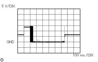
Waveform 2
i.
0.24,1.406 0.552,1.583
0.313,0.177
10
false
GND
0.063,0.146 0.656,0.313
0.594,0.167
10
false
5 V/DIV.
2.552,1.875 3.385,2.073
0.833,0.198
10
false
100 ms./DIV.
When a gear is engaged and switching is performed
| Item | Content |
|---|---|
| Tester Connection | C40-8 (TM1) - C40-10 (GND) |
| Tool Setting | 5 V/DIV., 100 ms./DIV. |
| Condition | Ignition switch ON
Shift lever in N*1 Shift lever in neutral*2 Transfer position switch turned from L4 to H4 (switching from L4 to H4) |
*1: for Automatic Transmission
*2: for Manual Transmission
| Item | Content |
|---|---|
| Tester Connection | C40-7 (TM2) - C40-10 (GND) |
| Tool Setting | 5 V/DIV., 100 ms./DIV. |
| Condition | Ignition switch ON
Shift lever in N*1 Shift lever in neutral*2 Transfer position switch turned from H2 to H4 (switching from H2 to H4) Transfer position switch turned from H4 to L4 (switching from H4 to L4) |
*1: for Automatic Transmission
*2: for Manual Transmission
ii.
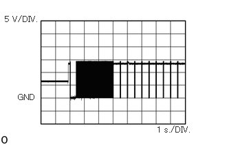
0.073,0.219 0.677,0.375
0.604,0.156
10
false
5 V/DIV.
2.375,1.885 2.99,2.083
0.615,0.198
10
false
1 s./DIV.
0.271,1.396 0.729,1.594
0.458,0.198
10
false
GND
When a gear is not engaged and switching is not performed
| Item | Content |
|---|---|
| Tester Connection | C40-8 (TM1) - C40-10 (GND) |
| Tool Setting | 5 V/DIV., 1 s./DIV. |
| Condition | Ignition switch ON
Shift lever in N*1 Shift lever in neutral*2 Transfer position switch turned from L4 to H4 (switching from L4 to H4) |
*1: for Automatic Transmission
*2: for Manual Transmission
| Item | Content |
|---|---|
| Tester Connection | C40-7 (TM2) - C40-10 (GND) |
| Tool Setting | 5 V/DIV., 1 s./DIV. |
| Condition | Ignition switch ON
Shift lever in N*1 Shift lever in neutral*2 Transfer position switch turned from H2 to H4 (switching from H2 to H4) Transfer position switch turned from H4 to L4 (switching from H4 to L4) |
*1: for Automatic Transmission
*2: for Manual Transmission