R151F MANUAL TRANSMISSION / TRANSAXLE MANUAL TRANSMISSION UNIT INSPECTION
PROCEDURE

 33428
1.INSPECT COUNTERSHAFT 5TH GEAR
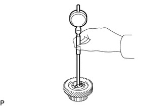
Using a cylinder gauge, measure the inside diameter of the countershaft 5th gear.
- Standard inside diameter:
38.015 to 38.040 mm (1.4967 to 1.4976 in.)
- Maximum inside diameter:
38.040 mm (1.4976 in.)
If the inside diameter is more than the maximum, replace the countershaft 5th gear.
2.INSPECT COUNTERSHAFT 5TH GEAR THRUST CLEARANCE
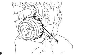
Using a feeler gauge, measure the thrust clearance.
- Standard clearance:
0.10 to 0.35 mm (0.00394 to 0.0137 in.)
If the clearance is not as specified, replace the countershaft 5th gear.
3.INSPECT COUNTERSHAFT 5TH GEAR RADIAL CLEARANCE
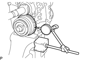
Using a dial indicator, measure the radial clearance.
- Standard clearance:
0.015 to 0.068 mm (0.000591 to 0.00267 in.)
If the clearance is not as specified, replace the counter 5th gear bearing.
33368
4.INSPECT NO. 2 SYNCHRONIZER RING
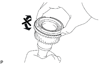
Apply gear oil to the cone of the input shaft, and check that it does not turn in either direction while pushing the No. 2 synchronizer ring.
If it can turn, replace the No. 2 synchronizer ring.
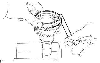
Push the No. 2 synchronizer ring against the cone of the input shaft. Measure the clearance between the No. 2 synchronizer ring and input shaft.
- Standard clearance:
0.7 to 1.7 mm (0.0276 to 0.0669 in.)
If the clearance is not as specified, replace the No. 2 synchronizer ring.
33384A
5.INSPECT NO. 3 SYNCHRONIZER RING
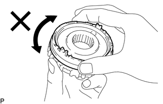
Apply gear oil to the cone part of the No. 5 gear spline piece, and check that it does not turn in either direction while pushing the No. 3 synchronizer ring against the No. 5 gear spline piece.
If it can turn, replace the No. 3 synchronizer ring.
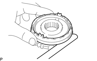
Push the No. 3 synchronizer ring against the cone part of the No. 5 gear spline piece. Measure the clearance between the No. 3 synchronizer ring and No. 5 gear spline piece.
- Standard clearance:
0.68 to 1.32 mm (0.0268 to 0.0519 in.)
If the clearance is not as specified, replace the No. 3 synchronizer ring.
33212A
6.INSPECT NO. 1 GEAR SHIFT FORK
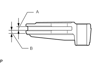
Using a vernier caliper, measure the No. 1 gear shift fork groove A and the thickness B.
- Standard groove (A):
5.20 to 5.36 mm (0.205 to 0.211 in.)
- Maximum groove (A):
5.36 mm (0.211 in.)
- Standard thickness (B):
4.35 to 4.65 mm (0.172 to 0.183 in.)
- Minimum thickness (B):
4.35 mm (0.172 in.)
If the width is not as specified, replace the No. 1 gear shift fork.
33213G
7.INSPECT NO. 2 GEAR SHIFT FORK
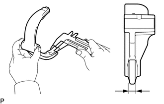
Using a vernier caliper, measure the thickness of the claw part of the No. 2 gear shift fork.
- Standard thickness:
9.9 to 10.0 mm (0.390 to 0.393 in.)
- Minimum thickness:
9.9 mm (0.390 in.)
If the width is not as specified, replace the No. 2 gear shift fork.
33214G
8.INSPECT NO. 3 GEAR SHIFT FORK
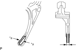
| *a | Pad |
Using a vernier caliper, measure the thickness of the claw part of the No. 3 gear shift fork.
- Standard thickness:
9.76 to 10.24 mm (0.385 to 0.403 in.)
- Minimum thickness:
9.76 mm (0.385 in.)
- NOTICE:
-
Check the thickness including the pad.
If the measurement result is less than the minimum or the pad is damaged, replace the No. 3 gear shift fork.
33395
9.INSPECT NO. 3 TRANSMISSION HUB SLEEVE
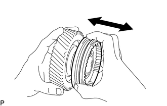
Check the sliding condition between the countershaft 5th gear and No. 3 transmission hub sleeve.
Check the spline gear of the No. 3 transmission hub sleeve for wear.
If there are any defects, replace the No. 3 transmission hub sleeve.
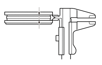
Using a vernier caliper, measure the No. 3 transmission hub sleeve groove.
- Standard groove:
10.5 to 10.6 mm (0.414 to 0.417 in.)
- Maximum groove:
10.6 mm (0.417 in.)
If the width is not as specified, replace the No. 3 transmission hub sleeve.
33402
10.INSPECT REVERSE IDLER GEAR SUB-ASSEMBLY
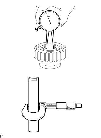
Using a caliper gauge, measure the inside diameter of the reverse idler gear sub-assembly.
- Standard inside diameter:
24.040 to 24.061 mm (0.9465 to 0.9472 in.)
- Maximum inside diameter:
24.061 mm (0.9472 in.)
If the inside diameter is more than the maximum, replace the reverse idler gear sub-assembly.
Using a micrometer, measure the diameter of the sliding part of the reverse idler gear sub-assembly on the reverse idler gear shaft.
- Standard diameter:
23.979 to 24.000 mm (0.9441 to 0.9448 in.)
- Minimum diameter:
23.979 mm (0.9441 in.)
If the diameter is less than the minimum, replace the reverse idler gear shaft.
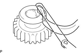
Using a feeler gauge, measure the thrust clearance of the shoe part between the reverse idler gear sub-assembly and reverse shift arm.
- Standard clearance:
0.05 to 0.35 mm (0.00197 to 0.0137 in.)
If the clearance is not as specified, replace the reverse idler gear sub-assembly and reverse shift arm.