1GD-FTV STARTING STARTER(for 2.2 kW Type) REASSEMBLY
PROCEDURE

 1.INSTALL RUBBER SEAL
Install the rubber seal to the starter drive housing.
28140
2.INSTALL STARTER BRUSH HOLDER ASSEMBLY
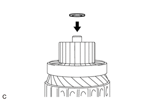
Install the washer to the starter armature assembly.
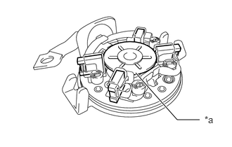
| *a | Assembly Washer |
When reusing the starter brush holder, lift up assembly washer and secure it with the brushes.
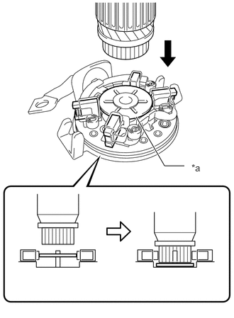
| *a | Plate A |
Install the starter armature to the starter brush holder.
- HINT:
-
Press down assembly washer of the starter brush holder with the starter armature to install the starter armature as shown in the illustration.
28160
3.INSTALL STARTER ARMATURE ASSEMBLY
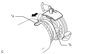
| *a | Cutout |
| *b | Rubber Part |
Install the starter armature assembly together with the starter brush holder assembly to the starter yoke assembly.
- NOTICE:
-
Align the cutout of the starter yoke assembly with the rubber part and install the starter brush holder assembly.
28120
4.INSTALL STARTER YOKE ASSEMBLY
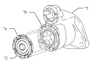
| *1 | Starter Drive Housing |
| *2 | Starter Armature Plate |
| *a | Cutout |
| *b | Protrusion |
Fit the 2 cutouts of the starter armature plate into the 2 protrusions of the ring gear support to install the starter armature plate to the starter drive housing.
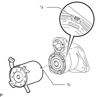
| *a | Protrusion |
| *b | Cutout |
Align the cutout of the starter yoke assembly and the protrusion of the starter drive housing and install the starter yoke assembly to the starter drive housing.
Using a 7 mm socket wrench, install the 2 bolts.
- Torque:
- 7.9 N*m (81 kgf*cm, 70 in.*lbf)
28150
5.INSTALL MAGNET STARTER SWITCH ASSEMBLY
Install the plate to the plunger.
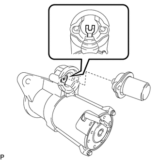
Hang the hook of the plunger on the pinion drive lever and install the plunger.
Install the return spring to the magnet starter switch assembly.
Install the magnet starter switch assembly to the starter drive housing with the 2 screws.
- Torque:
- 7.4 N*m (75 kgf*cm, 65 in.*lbf)
Connect the lead wire to terminal C with the nut.
- Torque:
- 9.8 N*m (100 kgf*cm, 87 in.*lbf)