FRONT SUSPENSION FRONT UPPER SUSPENSION ARM(for 4WD and Pre-Runner) REMOVAL
CAUTION / NOTICE / HINT
The necessary procedures (adjustment, calibration, initialization, or registration) that must be performed after parts are removed, installed, or replaced during the front upper suspension arm removal/installation are shown below.
- Necessary Procedure After Parts Removed/Installed/Replaced:
Replacement Part or Procedure Necessary Procedures Effects/Inoperative when not Performed Link Front wheel alignment adjustment ·Clearing zero point calibration data
·Yaw rate and acceleration sensor zero point calibration
·DTCs are output
·ABS warning light illumination
·Slip indicator light illumination
·VSC disable or malfunctioning
(  )
w/ Automatic Headlight Beam Level Control System:
The vehicle height changes due to replacement of suspension components or after performing such operations as removal and reinstallation
Headlight leveling ECU assembly initialization Headlight leveling function ( )
- HINT:
- ·
Use the same procedure for the RH and LH sides
·The procedure listed below is for the LH side.
PROCEDURE

 1.REMOVE FRONT WHEEL
89543
2.DISCONNECT FRONT SPEED SENSOR LH
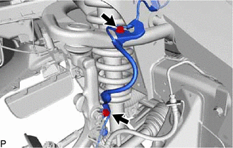
Remove the 2 bolts and disconnect the front speed sensor LH.
48810
3.DISCONNECT FRONT STABILIZER LINK ASSEMBLY LH
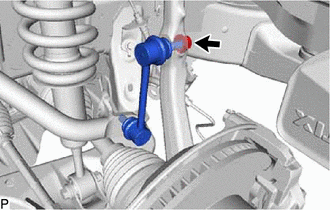
Remove the nut and disconnect the front stabilizer link assembly LH from the steering knuckle.
- HINT:
-
If the ball joint turns together with the nut, use a 6 mm hexagon wrench to hold the stud in place.
48630
4.REMOVE FRONT UPPER SUSPENSION ARM ASSEMBLY LH
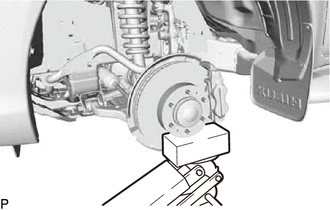
Support the lower arm with a jack.
Remove the clip and nut.
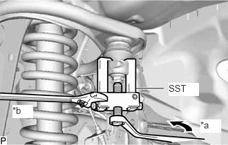
| *a | Turn |
| *b | Hold |
Using SST, disconnect the front upper ball joint from the steering knuckle.
- SST
- 09628-62011
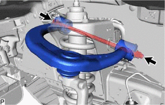
Remove the nut, 2 retainers and bolt.
Remove the front upper suspension arm assembly LH.
48632B
5.REMOVE FRONT UPPER SUSPENSION ARM BUSH LH
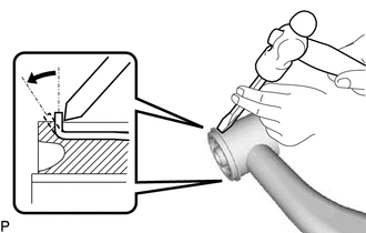
Using a hammer and chisel, strike and bend the entire flange of the bush as shown in the illustration.
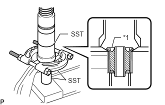
| *1 | Front Upper Suspension Arm Bush LH |
Using SST and a press, press out the front upper suspension arm bush LH.
- SST
- 09613-26010
09710-22021 (09710-01061)
09950-00020
6.REMOVE UPPER BALL JOINT DUST COVER
Remove the dust cover set ring and upper ball joint dust cover from the front upper suspension arm assembly LH.
- NOTICE:
- ·
Do not damage the upper ball joint dust cover.
·If the upper ball joint dust cover is damaged, replace it.
43360
7.REMOVE FRONT UPPER BALL JOINT
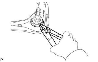
Using a snap ring expander, remove the snap ring.
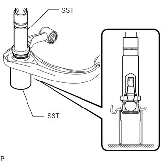
Using SST and a press, press out the front upper ball joint.
- SST
- 09612-30012
09388-40010