FRONT SUSPENSION FRONT LOWER SUSPENSION ARM(for 4WD and Pre-Runner) INSTALLATION
CAUTION / NOTICE / HINT
- HINT:
- ·
Use the same procedure for the RH and LH sides.
·The procedure listed below is for the LH side.
PROCEDURE

 48304
1.INSTALL FRONT NO. 1 SPRING BUMPER SUB-ASSEMBLY
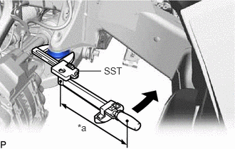
| *a | Torque Wrench Fulcrum Length |
Using SST, install the front spring bumper to the vehicle.
- Torque:
- Specified tightening torque : 31 N*m (316 kgf*cm, 23 ft.*lbf)
- HINT:
- ·
Calculate the torque wrench reading when changing the fulcrum length of the torque wrench.
Click hereGeneral>INTRODUCTION>REPAIR INSTRUCTION>PRECAUTION
·When using SST (fulcrum length of 69.68 mm (2.7433 in.)) + torque wrench (fulcrum length of 300 mm (11.8110 in.)): 25.2 N*m (257 kgf*cm, 19 ft.*lbf)
43340A
2.INSTALL FRONT LOWER BALL JOINT ASSEMBLY LH
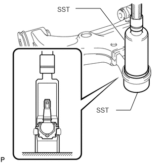
Using SST and press, press in a new front lower ball joint assembly LH.
- SST
- 09226-10010
09631-32020
Install a new snap ring.
- NOTICE:
-
Make sure the snap ring is securely installed in the groove.
48655E
3.INSTALL FRONT NO. 2 LOWER ARM BUSH
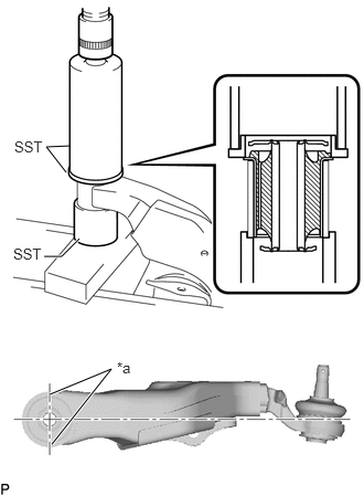
| *a | Bush Positioning Protrusion |
Using SST and a press, install a new front No. 2 lower arm bush.
- SST
- 09502-12010
09513-36040
09710-14013 (09710-00021)
- NOTICE:
-
Press the bush while making sure the bush positioning protrusions are perpendicular to the lower arm as shown in the illustration.
48654F
4.INSTALL FRONT NO. 1 LOWER ARM BUSH
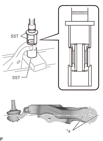
| *a | Bush Positioning Protrusion |
Using SST and a press, press in a new front No. 1 lower arm bush.
- SST
- 09710-14013 (09710-00021)
09710-20011 (09710-06041)
09950-60010 (09951-00650)
- NOTICE:
-
Press the bush while making sure the bush positioning protrusions are perpendicular to the lower arm as shown in the illustration.
48626
5.INSTALL FRONT LOWER BALL JOINT ATTACHMENT LH
Install the front lower ball joint attachment LH with a new nut and a new cotter pin.
- Torque:
- 140 N*m (1428 kgf*cm, 103 ft.*lbf)
48069
6.TEMPORARILY INSTALL FRONT LOWER NO. 1 SUSPENSION ARM SUB-ASSEMBLY LH
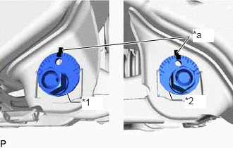
| *1 | No. 1 Camber Adjusting Cam |
| *2 | No. 2 Camber Adjusting Cam |
| *a | Matchmark |
Temporarily install the front lower No. 1 suspension arm sub-assembly LH, and No. 1 and No. 2 camber adjusting cams with the No. 1 and No. 2 camber adjusting cam assemblies and 2 nuts.
Align the matchmarks on the No. 1 camber adjusting cam and No. 2 camber adjusting cam with the corresponding matchmarks on the vehicle frame.
Install the front lower ball joint attachment LH with the 2 bolts.
- Torque:
- 160 N*m (1632 kgf*cm, 118 ft.*lbf)
7.TEMPORARILY INSTALL FRONT SHOCK ABSORBER WITH COIL SPRING
Temporarily install the front shock absorber with coil spring with the bolt and nut.
8.INSTALL FRONT WHEEL
9.STABILIZE SUSPENSION
48069
10.TIGHTEN FRONT LOWER NO. 1 SUSPENSION ARM SUB-ASSEMBLY LH
Tighten the 2 nuts.
- Torque:
- 185 N*m (1886 kgf*cm, 136 ft.*lbf)
11.TIGHTEN FRONT SHOCK ABSORBER WITH COIL SPRING
Fix the nut in place and tighten the bolt.
- Torque:
- 110 N*m (1122 kgf*cm, 81 ft.*lbf)
- NOTICE:
-
Do not tighten the nut.
4866A
12.INSTALL FRONT LOWER ARM SHAFT BOOT PROTECTOR LH (w/ Drive Shaft Boot Protector)
Install the front lower arm shaft boot protector LH with the 2 bolts.
- Torque:
- 30 N*m (306 kgf*cm, 22 ft.*lbf)
51442
13.INSTALL NO. 2 ENGINE UNDER COVER
51410
14.INSTALL NO. 1 ENGINE UNDER COVER ASSEMBLY
15.INSPECT AND ADJUST FRONT WHEEL ALIGNMENT
16.PERFORM INITIALIZATION (w/ Automatic Headlight Beam Level Control System)
17.INSPECT AUTOMATIC LIGHT CONTROL SYSTEM (w/ Automatic Headlight Beam Level Control System)
18.INSPECT HEADLIGHT AIMING (w/ Automatic Headlight Beam Level Control System)